Advertisement
Quick Links
DESCRIPTION
WARNING!
Do not look directly at operating LED.
This circuit produces light that can damage eyes.
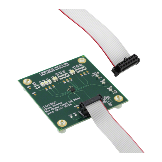
Demonstration circuit 1055 is a 250mA Universal Nine
Channel LED Driver with two RGB displays and three
white LEDs featuring the LTC3219.
The LTC3219 is a low noise charge pump designed to
drive nine universal LED current sources. The LTC3219
requires only five small ceramic capacitors to form a
complete LED power supply and current controller.
The maximum display currents are set with an internal
precision current reference. On/Off blinking, gradation,
and intensity are achieved via an I
QUICK START PROCEDURE
Demonstration circuit 1055 is easy to set up to evaluate
the performance of the LTC3219. Refer to Figure 1 for
proper measurement equipment setup and follow the
procedure below:
NOTE. When measuring the input or output voltage ripple, care must be
taken to avoid a long ground lead on the oscilloscope probe. Measure the
input or output voltage ripple by touching the probe tip directly across the
VBAT and GND terminals. See Figure 2 for proper scope probe technique.
1. Refer to the DC590 Quick Start Guide for QuikEval
setup and software installation details.
2. Make sure the USB cable is connected between the
computer and the DC590 controller board.
NOTE. If using the DC590B board, a specific DVCC voltage level
may be selected. This is done by setting the VCCIO jumper on the
DC590 board to one of the following settings: 3.3V, 5V, removed
for 2.7V or set to external if use of an external supply is desired.
2
C serial interface. See
TM
Demo Circuit 1055
QUICK START GUIDE
250mA Universal Nine
Channel LED Driver
the LTC3219 data sheet for more information on this
process. There are 64 dimming states available for the
universal LEDs.
The charge pump optimizes efficiency based on the volt-
age across the LED current sources. The part powers up
in 1x mode and will automatically switch to boost mode
whenever any enabled LED current source begins to drop
out. The first dropout switches the part to 1.5x mode and
a subsequent dropout switches the part into 2x mode.
The part resets to 1x mode whenever a data byte is up-
2
dated via the I
C port.
Design files for this circuit board are available. Call
the LTC factory.
L
, LTC, LTM, LT are registered trademarks of Linear Technology Corporation. Other product
names may be trademarks of the companies that manufacture the products.
3. Connect DC1055 to the DC590 USB Serial Controller
using the supplied 14-conductor ribbon cable as
shown in Figure 1.
4. With power off, connect the input power supply to
VBAT and GND with a series ammeter and a voltmeter
as shown in Figure 1.
5. Turn on and set the input power supply between 2.9 –
5.5V. The DC1055 has an extra 4.7uF de-coupling ca-
pacitor between VBAT and GND to help accommodate
long VBAT source lead lengths. The DC590 board gets
its power from the USB cable.
NOTE. Make sure that the input voltage does not exceed 6V.
6. Run the QuikEval program. The program detects the
DC1055 and displays the LTC3219 control window
(shown in Figure 3).
LTC3219
LTC3219
1
Advertisement

Subscribe to Our Youtube Channel
Related Manuals for Linear Technology DC1055A


Summary of Contents for Linear Technology DC1055A
- Page 1 LTC factory. The maximum display currents are set with an internal , LTC, LTM, LT are registered trademarks of Linear Technology Corporation. Other product precision current reference. On/Off blinking, gradation, names may be trademarks of the companies that manufacture the products.
- Page 2 LTC3219 Figure 1. Proper Measurement Equipment Setup Figure 2. Measuring Input or Output Ripple...
- Page 3 VIEW LTC3219 PRODUCT PAGE button opens an inter- BLUE vertical slide control adjusts the intensity for se- net browser and searches the Linear Technology Corpo- lected universal LEDs U6 and U9 from 0 to 28mA in 64 ration web site for information on the LTC3219 when an steps.
- Page 4 LTC3219 when the GRADATE UP, GRADATE DOWN, START BLINK ULEDs button blinks or stop blinking the selected GRADATION WITH ENU or DEMO 1 button is selected. If LEDs at the on-time and period selected by the BLINK the DISABLED option button is selected, the universal ONt/PERIOD option buttons and at the selected LED in- LEDs will not gradate when any of the GRADATION con- tensity.
- Page 5 LTC3219 Figure 3. LTC3219 Control Window...
- Page 6 LTC3219...
- Page 7 LTC3219...
- Page 8 Mouser Electronics Authorized Distributor Click to View Pricing, Inventory, Delivery & Lifecycle Information: Analog Devices Inc. DC1055A...
Need help?
Do you have a question about the DC1055A and is the answer not in the manual?
Questions and answers