Advertisement
Quick Links
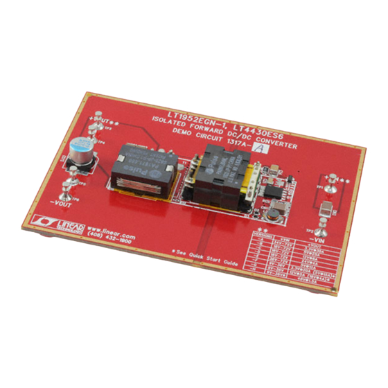
QUICK START GUIDE FOR DEMONSTRATION CIRCUIT 1317A-A
ACTIVE RESET ISOLATED 48V INPUT TO 3.3V @30A DC/DC POWER CONVERTER
DESCRIPTION
DESCRIPTION
DESCRIPTION
DESCRIPTION
Demonstration circuit 1317A-A is isolated input to
high current output 1/8th Brick footprint
1/8th Brick footprint converter
1/8th Brick footprint
1/8th Brick footprint
featuring the LT ® 1952 switching controller with Ac-
tive Reset circuit. The Active Reset circuit can im-
prove the efficiency in wide input voltage applica-
tions. Also, the Active Reset allows the implementa-
tion of self-driven synchronous secondary rectifiers
in some applications.
The DC1317A-A converts isolated 34V to 75V input to
3.3V output and provides over 30A of output current.
The converter operates at 300kHz with the peak effi-
ciency greater than 93%. The DC1317 can be easily
modified to generate output voltages in the range
from 0.6V to 48V. The output currents are limited by
total output power of up to 150W.
The other available versions of DC1317A are:
DC1317A-B, 18-72Vin to 5V, 25A
DC1317A-C, 18-72Vin to 12V, 10A
DC1317A-D, 18-72Vin to 24V, 5A
DC1317A-E, 36-72Vin to 5V, 12A
Performance Summary
Performance Summary
Performance Summary
Performance Summary
Table 1.
Table 1.
Table 1.
Table 1.
PARAMETER
PARAMETER
PARAMETER
PARAMETER
Minimum Input Voltage
Maximum Input Voltage
V OUT
Typical Output Ripple V OUT
Nominal Switching Frequency
QUICK START PROCEDUR
QUICK START PROCEDURE E E E
QUICK START PROCEDUR
QUICK START PROCEDUR
Demonstration circuit 1317 is easy to set up to evalu-
ate the performance of LT1952 circuit. Refer to Fi
DC1317A-F, 9-36Vin to 3.3V, 20A
DC1317A-G, 9-36Vin to 12V, 5A
DC1317A-H, 9-36Vin to 48V, 1.5A
The DC1317 circuit features soft-start which prevents
output voltage overshoot on startup or when recover-
ing from overload condition.
The DC1317 has precise over-current protection cir-
cuit that allows for continuous operation under short
circuit conditions. The low power dissipation under
short circuit conditions insures high reliability even
during short circuits.
The LT1952 can be synchronized to an external clock
of up to 400kHz. Please refer to LT1952 data sheet for
design details and applications information.
Design files for this circuit board are avai
Design files for this circuit board are avail l l l able.
Design files for this circuit board are avai
Design files for this circuit board are avai
Call the LTC factory.
Call the LTC factory.
Call the LTC factory.
Call the LTC factory.
LT is a trademark of Linear Technology Corporation
CONDITION
CONDITION
CONDITION
CONDITION
I OUT = 0A to 30A
I OUT = 0A to 30A
V IN = 34V to 75V, I OUT = 0A to 30A
V IN = 34V to 75V, I OUT = 0A to 30A
ure 1 for proper measurement equipment setup
ure 1 for proper measurement equipment setup
ure 1 for proper measurement equipment setup
ure 1 for proper measurement equipment setup
Refer to Fig- g- g- g-
and follow the procedure below:
Refer to Fi
Refer to Fi
LT1952
able.
able.
able.
VALUE
VALUE
VALUE
VALUE
34V
75V
3.3V ±3%
50mV P–P
300kHz
1
Advertisement

Related Manuals for Linear Technology 1317A-A


Summary of Contents for Linear Technology 1317A-A
- Page 1 QUICK START GUIDE FOR DEMONSTRATION CIRCUIT 1317A-A ACTIVE RESET ISOLATED 48V INPUT TO 3.3V @30A DC/DC POWER CONVERTER LT1952 DESCRIPTION DESCRIPTION DESCRIPTION DESCRIPTION Demonstration circuit 1317A-A is isolated input to DC1317A-F, 9-36Vin to 3.3V, 20A high current output 1/8th Brick footprint...
- Page 2 QUICK START GUIDE FOR DEMONSTRATION CIRCUIT 1317A-A ACTIVE RESET ISOLATED 48V INPUT TO 3.3V @30A DC/DC POWER CONVERTER NOTE: NOTE: When measuring the input or output voltage NOTE: NOTE: If there is no output, temporarily disconnect the ripple, care must be taken to avoid a long ground lead load to make sure that the load is not set too high.
- Page 3 QUICK START GUIDE FOR DEMONSTRATION CIRCUIT 1317A-A ACTIVE RESET ISOLATED 48V INPUT TO 3.3V @30A DC/DC POWER CONVERTER Figure 2. Scope Probe Placement for Measuring Input or Output Ri Figure 2. Scope Probe Placement for Measuring Input or Output Rip p p p ple Figure 2.
-
Page 4: Soft Start Function
QUICK START GUIDE FOR DEMONSTRATION CIRCUIT 1317A-A ACTIVE RESET ISOLATED 48V INPUT TO 3.3V @30A DC/DC POWER CONVERTER remove the resistor R1 and connect 48V, 100mA power source to +Vb node (right side of R1). By doing this, the primary PWM controller LT1952 can be activated without the main primary power being applied to +Vin. - Page 5 QUICK START GUIDE FOR DEMONSTRATION CIRCUIT 1317A-A ACTIVE RESET ISOLATED 48V INPUT TO 3.3V @30A DC/DC POWER CONVERTER by placing the associated components close to the If the PCB layout has to be done on 2 or 4-layer PCB LT1952 and LT4430 chips.
- Page 6 QUICK START GUIDE FOR DEMONSTRATION CIRCUIT 1317A-A ACTIVE RESET ISOLATED 48V INPUT TO 3.3V @30A DC/DC POWER CONVERTER +Vin PBSS8110 7, 8 +Vin +Vout PA1671.650 2.2R 1.5mH 2.2R +Vr2 BAS516 9, 10, 11 2x2.2uF PDZ10B -Vin HAT2165 2, 3 PA0861.004 +Vin 0.22uf...
- Page 7 QUICK START GUIDE FOR DEMONSTRATION CIRCUIT 1317A-A ACTIVE RESET ISOLATED 48V INPUT TO 3.3V @30A DC/DC POWER CONVERTER...
- Page 8 QUICK START GUIDE FOR DEMONSTRATION CIRCUIT 1317A-A ACTIVE RESET ISOLATED 48V INPUT TO 3.3V @30A DC/DC POWER CONVERTER...
Need help?
Do you have a question about the 1317A-A and is the answer not in the manual?
Questions and answers