Advertisement
5MHz to 27MHz, Pin Configurable, Fully Differential, 2
DESCRIPTION
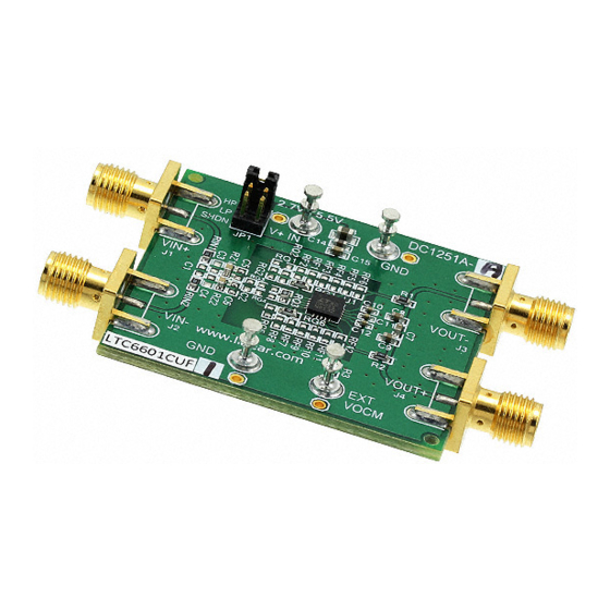
Demonstration Circuit DC1251A features the LTC6601-X
series family of pin configurable, fully differential, 2
der lowpass filter and amplifier.
There are two DC1251A boards: a DC1251A-A with an
LTC6601-1 and a DC1251A-B with an LTC6601-2.
Typically an LTC6601-1 is the choice for most lowpass
filter applications in a 5MHz to 27MHz cutoff frequency
range and the LTC6601-2 is optimized for lower distor-
tion and lower power applications.
The LTC6601-X is designed to make the implementation
of high frequency fully-differential filtering functions very
easy. A very low noise amplifier is surrounded by 8 preci-
sion matched resistors and 12 precision matched capaci-
nd
tors so that many 2
order lowpass filter transfer func-
tions can be configured by hard wiring pins.
Figure 1 shows the LTC6601-X block diagram with all the
internal resistors and capacitors. On a DC1251A the
LTC6601-X resistor and capacitor pins can be connected
through 0603 resistor jumpers to configure the cutoff
frequency and the passband gain. The LTC6601-1 or
LTC6601-2 data sheet contains tables and circuits for
configuring the pins for a variety of cutoff frequencies
and passband gains (The cutoff or -3dB frequency is a
function of the fo frequency and Q value, refer to the Fig-
ure 3 filter equations in the LTC6601-1 data sheet).
Figure 2 shows an example of an LTC6601-1 configured
nd
as a 2
order lowpass filter with a 10MHz -3dB frequency
and a passband gain equal to 1 (0dB). The DC1251A-A/B
demonstration circuit default configuration is the circuit
of Figure 2.
The DC1251A has SMA connectors for the differential
input and output, a jumper with shunts to set the
LTC6601-X to high power (HP), low power (LP) or shut-
down (SHDN) operation and turrets to connect an exter-
nal VOCM. A DC1251A board operates with a single 2.7V
to 5.5V power supply.
Design files for these circuit boards are available.
Call the LTC factory.
, LTC and LT are registered trademarks of Linear Technology Corporation.
Figure 1. An LTC6601-X Block Diagram.
nd
or-
Figure 2. The LTC6601-X Circuit as configured in a
DC1251A assembly.
DEMO CIRCUIT 1251
QUICK START GUIDE
LTC6601-1, LTC6601-2
nd
Order Lowpass Filter
1
Advertisement
Table of Contents

Subscribe to Our Youtube Channel
Related Manuals for Linear Technology 1251


Summary of Contents for Linear Technology 1251
- Page 1 (SHDN) operation and turrets to connect an exter- nal VOCM. A DC1251A board operates with a single 2.7V to 5.5V power supply. Design files for these circuit boards are available. Call the LTC factory. , LTC and LT are registered trademarks of Linear Technology Corporation.
- Page 2 DEMO CIRCUIT 1251 QUICK START GUIDE 5MHZ TO 27MHZ, PIN CONFIGURABLE, FULLY DIFFERENTIAL, 2 ORDER LOWPASS FILTER QUICK TEST SET-UP Figure 3. A Quick Test Set-Up. Quick Test Procedure 5. Channel 1 and channel 2 on the oscilloscope should each show a 1MHz, 0.5Vp-p sine- Test Equipment: wave.
- Page 3 DEMO CIRCUIT 1251 QUICK START GUIDE 5MHZ TO 27MHZ, PIN CONFIGURABLE, FULLY DIFFERENTIAL, 2 ORDER LOWPASS FILTER CONFIGURING A DC1251 BOARD The modified topology’s C3 (the capacitor between The basic filter topology shown in Figure 4, can im- the summing junction) implements lower Q values plement most LTC6601-X lowpass filter circuits.
- Page 4 DEMO CIRCUIT 1251 QUICK START GUIDE 5MHZ TO 27MHZ, PIN CONFIGURABLE, FULLY DIFFERENTIAL, 2 ORDER LOWPASS FIL Figure 6. An LTC6601-1, Figure 4 circuit, configured as a 7MHz, lowpass filter with 12dB gain. Figure 7. DC1251A configured as the Figure 6 circuit.
- Page 5 DEMO CIRCUIT 1251 QUICK START GUIDE 5MHZ TO 27MHZ, PIN CONFIGURABLE, FULLY DIFFERENTIAL, 2 ORDER LOWPASS FIL Figure 8. An LTC6601-1, Figure 5 circuit, configured as a 5MHz, lowpass filter with 0dB gain. Figure 9. DC1251A configured as the Figure 8 circuit.
- Page 6 DEMO CIRCUIT 1251 QUICK START GUIDE DEMO CIRCUIT 1251 QUICK START GUIDE 5MHZ TO 27MHZ, PIN CONFIGURABLE, FULLY DIFFERENTIAL, 2 5MHZ TO 27MHZ, PIN CONFIGURABLE, FULLY DIFFERENTIAL, 2 ORDER LOWPASS FILTER ORDER LOWPASS FILTER...
- Page 7 DEMO CIRCUIT 1251 QUICK START GUIDE 5MHZ TO 27MHZ, PIN CONFIGURABLE, FULLY DIFFERENTIAL, 2 ORDER LOWPASS FILTER DC1251A Parts List...
- Page 8 Mouser Electronics Authorized Distributor Click to View Pricing, Inventory, Delivery & Lifecycle Information: Analog Devices Inc. DC1251A-A DC1251A-B...
Need help?
Do you have a question about the 1251 and is the answer not in the manual?
Questions and answers