Table of Contents
Advertisement
Quick Links
Advertisement
Table of Contents

Subscribe to Our Youtube Channel
Summary of Contents for Sentera Controls DPS-X-2
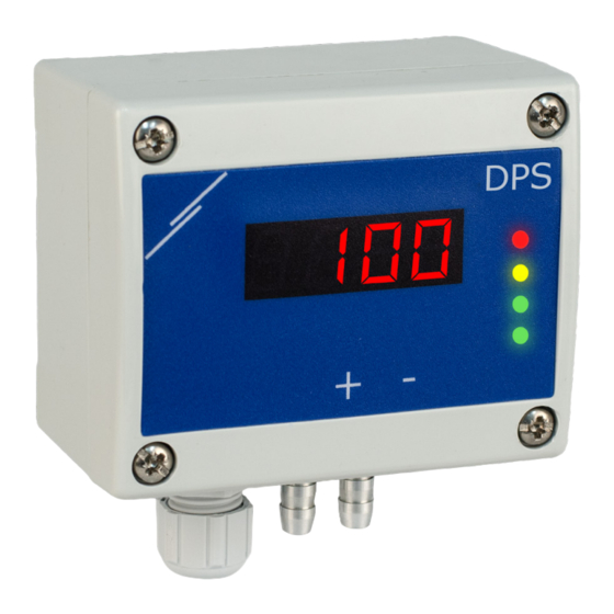
- Page 1 DPS-X -2 DIFFERENTIAL PRESSURE TRANSMITTER Mounting and operating instructions...
-
Page 2: Table Of Contents
OPERATIONAL DIAGRAMS WIRING AND CONNECTIONS MOUNTING INSTRUCTIONS IN STEPS VERIFICATION OF THE INSTALLATION INSTRUCTIONS OPERATING INSTRUCTIONS MODBUS REGISTER MAPS TRANSPORT AND STOCK KEEPING INFORMATION WARRANTY INFORMATION AND RESTRICTIONS MAINTENANCE MIW-DPS-X-2-EN-000 - 25 / 05 / 2023 2 - 120 www.sentera.eu... -
Page 3: Dps
In case there are any questions that are not answered, please contact your technical support or consult a professional. MIW-DPS-X-2-EN-000 - 25 / 05 / 2023 3 - 120 www.sentera.eu... -
Page 4: Product Description
Accuracy: ±2 % of the operating range ■ Operating ambient conditions: ► Temperature: -5—65 °C ► Rel. humidity: < 95 % rH (non-condensing) ■ Storage temperature: -20—70 °C MIW-DPS-X-2-EN-000 - 25 / 05 / 2023 4 - 120 www.sentera.eu back to the table of contents... -
Page 5: Standards
Never connect the common ground or -G type articles to other devices powered by a DC voltage. Doing so might cause permanent damage to the connected devices. MIW-DPS-X-2-EN-000 - 25 / 05 / 2023 5 - 120 www.sentera.eu... -
Page 6: Mounting Instructions In Steps
To measure air velocity, use PSET-PT set and enable Pitot tube air velocity via holding register 64. In this case the K-factor of the fan has to be 0. MIW-DPS-X-2-EN-000 - 25 / 05 / 2023 6 - 120 www.sentera.eu... - Page 7 PWM output (via holding register 54 - see the Modbus Map). Fig. 6 PWM (Open collector) connection (JP1 disconnected) External pull-up resistor 50—100 kΩ External voltage PWM GND source (5—30 VDC) MIW-DPS-X-2-EN-000 - 25 / 05 / 2023 7 - 120 www.sentera.eu back to the table of contents...
-
Page 8: Verification Of The Installation Instructions
Fig. 7 Power / Modbus communication indication ATTENTION The status of the LEDs can be checked only when the unit is energised. Take the relevant safety measures! MIW-DPS-X-2-EN-000 - 25 / 05 / 2023 8 - 120 www.sentera.eu back to the table of contents... -
Page 9: Operating Instructions
Communication holding registers reset procedure: Put the jumper onto pins 1 and 2 of the P4 connector for more than 20 s while the device is powered (see Fig. 10 ). MIW-DPS-X-2-EN-000 - 25 / 05 / 2023 9 - 120 www.sentera.eu... - Page 10 In case the measured differential pressure is higher than the control range ► maximum limit, the display shows ‘HI’ every 3 seconds (see Fig. 12 b) . MIW-DPS-X-2-EN-000 - 25 / 05 / 2023 10 - 120 www.sentera.eu back to the table of contents...
- Page 11 Sensor element failure indication: In case of failure of sensor element or loss of communication with it, an ‘Err’ message is displayed and the red LED4 blinks. See Fig. 15. MIW-DPS-X-2-EN-000 - 25 / 05 / 2023 11 - 120 www.sentera.eu...
-
Page 12: Warranty Information And Restrictions
In case of heavy pollution, clean with a non-aggressive product. In these circumstances the unit should be disconnected from the supply. Pay attention that no fluids enter the unit. Only reconnect it to the supply when it is completely dry. MIW-DPS-X-2-EN-000 - 25 / 05 / 2023 12 - 120 www.sentera.eu...


Need help?
Do you have a question about the DPS-X-2 and is the answer not in the manual?
Questions and answers