Table of Contents
Advertisement
Quick Links
Advertisement
Table of Contents

Related Manuals for Sentera Controls HPS-X -2


Summary of Contents for Sentera Controls HPS-X -2
- Page 1 HPS-X -2 DIFFERENTIAL PRESSURE TRANSMITTER Mounting and operating instructions...
-
Page 2: Table Of Contents
HPS-X -2 DIFFERENTIAL PRESSURE TRANSMITTER Table of contents SAFETY AND PRECAUTIONS PRODUCT DESCRIPTION ARTICLE CODES INTENDED AREA OF USE TECHNICAL DATA STANDARDS OPERATIONAL DIAGRAM WIRING AND CONNECTIONS MOUNTING INSTRUCTIONS IN STEPS VERIFICATION OF THE INSTALLATION INSTRUCTIONS OPERATING INSTRUCTIONS MODBUS REGISTER MAPS... -
Page 3: Hps
HPS-X -2 DIFFERENTIAL PRESSURE TRANSMITTER SAFETY AND PRECAUTIONS Read all information, the datasheet, mounting instructions and wiring scheme before working with the product. For personal and equipment safety, and for optimum product performance, make sure you entirely understand the contents before installing, using, or maintaining this product. -
Page 4: Product Description
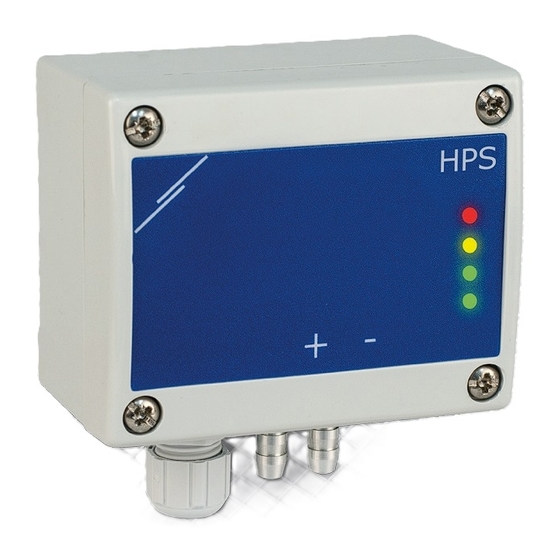
DIFFERENTIAL PRESSURE TRANSMITTER PRODUCT DESCRIPTION The HPS-X -2 series are high resolution differential pressure transmitters with Modbus RTU communication, which are equipped with a fully digital pressure transducer designed for a wide range of applications. Air flow velocity readout is available by connecting an external Pitot tube connection set. -
Page 5: Standards
HPS-X -2 DIFFERENTIAL PRESSURE TRANSMITTER ■ Modbus RTU communication ■ Sensor calibration procedure via tact switch ■ Aluminium pressure connection nozzles ■ Accuracy: ± 2 % of the operating range ■ Four LEDs with light guides for transmitter status indication ■... -
Page 6: Mounting Instructions In Steps
HPS-X -2 DIFFERENTIAL PRESSURE TRANSMITTER G and F-types devices cannot be used together in the same network. G and ATTENTION F-type devices must be supplied by separate power supplies. Do not connect the GND terminals of G and F-type devices together. -
Page 7: Verification Of The Installation Instructions
HPS-X -2 DIFFERENTIAL PRESSURE TRANSMITTER For sensor calibration and Modbus register reset procedures, refer to section NO T E “Operating instructions”. PWM voltage selection: ■ When the internal pull-up resistor (JP1) is connected , the voltage source is set via Modbus holding register 39, i.e. -
Page 8: Operating Instructions
HPS-X -2 DIFFERENTIAL PRESSURE TRANSMITTER ATTENTION The status of the LEDs can be checked only when the unit is energised. Take the relevant safety measures! The Network Bus Terminator (NBT) is controlled via Modbus RTU. By default the NBT is disconnected. For more information, see the Modbus Registers Maps below. - Page 9 HPS-X -2 DIFFERENTIAL PRESSURE TRANSMITTER Communication holding registers reset procedure: Put the jumper onto pins 1 and 2 of the P4 connector for more than 20 s while the device is powered. (See Fig. 8 Modbus holding register reset jumper ).
-
Page 10: Modbus Register Maps
HPS-X -2 DIFFERENTIAL PRESSURE TRANSMITTER MODBUS REGISTER MAPS INPUT REGISTERS Data type Description Data Values Output unsigned int. Output value in percentage 0—1.000 100 = 10,0% HPS-X-1K0 -2 0— 10.000 1.000 = 100,0 Pa HPS-X-2K0 -2 0— 20.000 1.000 =... - Page 11 HPS-X -2 DIFFERENTIAL PRESSURE TRANSMITTER HOLDING REGISTERS Data type Description Data Default Values Device slave address unsigned int. Modbus device address 1—247 4.800 9.600 19.200 Modbus baud rate unsigned int. Modbus communication baud rate 0—6 38.400 57.600 115.200 230.400 None Modbus parity mode unsigned int.
- Page 12 HPS-X -2 DIFFERENTIAL PRESSURE TRANSMITTER INPUT REGISTERS (see Table Input registers above) The input registers are read-only. All data can be read using the ‘Read Input Registers’ command. Table Input registers shows the returned data type and the way it should be interpreted.
- Page 13 HPS-X -2 DIFFERENTIAL PRESSURE TRANSMITTER The minimum pressure range cannot be higher than the maximum control range NO T E minus 50 Pa. ■ Holding register 12 defines the maximum pressure range. It cannot be set lower than the minimum pressure range plus the minimum pressure range span (i.e.
- Page 14 HPS-X -2 DIFFERENTIAL PRESSURE TRANSMITTER ■ Holding register 29 contains the value of the ‘Power-up timer’ before setting the alert and range limit flags. The default value is 60 s. During this interval the alerts and range limits are not compared with the current differential pressure / volume / velocity and alert and range limit flags registers remain ‘0’.
-
Page 15: Transport And Stock Keeping Information
HPS-X -2 DIFFERENTIAL PRESSURE TRANSMITTER TRANSPORT AND STOCK KEEPING INFORMATION Avoid shocks and extreme conditions; stock in original packing. WARRANTY INFORMATION AND RESTRICTIONS Two years from the delivery date against defects in manufacturing. Any modifications or alterations to the product after the date of publication relieve the manufacturer of any responsibilities.
Need help?
Do you have a question about the HPS-X -2 and is the answer not in the manual?
Questions and answers