Table of Contents
Advertisement
Quick Links
Advertisement
Table of Contents

Subscribe to Our Youtube Channel
Related Manuals for Sentera Controls HPS-X -2


Summary of Contents for Sentera Controls HPS-X -2
- Page 1 HPS-X -2 DIFFERENTIAL PRESSURE TRANSMITTER Mounting and operating instructions...
-
Page 2: Table Of Contents
HPS-X -2 DIFFERENTIAL PRESSURE TRANSMITTER Table of contents SAFETY AND PRECAUTIONS PRODUCT DESCRIPTION ARTICLE CODES INTENDED AREA OF USE TECHNICAL DATA STANDARDS OPERATIONAL DIAGRAM WIRING AND CONNECTIONS MOUNTING INSTRUCTIONS IN STEPS VERIFICATION OF THE INSTALLATION INSTRUCTIONS OPERATING INSTRUCTIONS TRANSPORT AND STORAGE... -
Page 3: Safety And Precautions
HPS-X -2 DIFFERENTIAL PRESSURE TRANSMITTER SAFETY AND PRECAUTIONS Read all the information, the datasheet, Modbus map, mounting and operating instructions and study the wiring and connection diagram before working with the product. For personal and equipment safety, and for optimum product performance, make sure you entirely understand the contents before installing, using, or maintaining this product. -
Page 4: Product Description
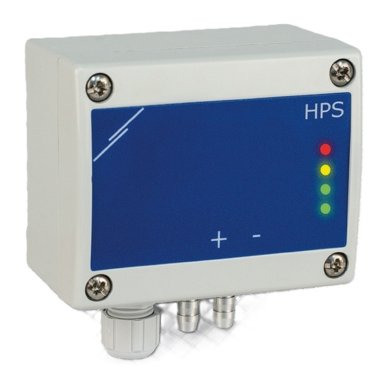
HPS-X -2 DIFFERENTIAL PRESSURE TRANSMITTER PRODUCT DESCRIPTION The HPS -2 series are differential pressure transmitters, which are equipped with a fully digital pressure transducer designed for a wide range of applications. Air velocity readout is available by connecting an external Pitot tube connection set. -
Page 5: Standards
HPS-X -2 DIFFERENTIAL PRESSURE TRANSMITTER STANDARDS ■ EMC Directive 2014/30/EC: ► EN 61326-1:2013 Electrical equipment for measurement, control and laboratory use - EMC requirements - Part 1: General requirements EN 61326-2-3:2013 Electrical equipment for measurement, control and ► laboratory use - EMC requirements - Part 2-3: Particular requirements - Test... -
Page 6: Mounting Instructions In Steps
HPS-X -2 DIFFERENTIAL PRESSURE TRANSMITTER The -F version of the product is not suited for 3-wire connection. It has separate ATTENTION grounds for power supply and analogue output. Connecting both grounds together might result in incorrect measurements. Minimum 4 wires are required to connect -F type sensors. - Page 7 HPS-X -2 DIFFERENTIAL PRESSURE TRANSMITTER Connect the nozzles to the duct (see Fig. 4). Depending the application you must use a specific connection set to connect the nozzles of the unit to the duct: To measure differential pressure, use PSET-QF or PSET-PVC set (pressure measurement is the unit default setting);...
-
Page 8: Verification Of The Installation Instructions
HPS-X -2 DIFFERENTIAL PRESSURE TRANSMITTER Fig. 6 PWM (Open collector) connection (JP1 disconnected) External pull-up resistor 50—100 kΩ External voltage PWM GND source (5—30 VDC) Optional settings To assure correct communication, the NBT needs to be activated in only two devices on the Modbus RTU network. -
Page 9: Operating Instructions
HPS-X -2 DIFFERENTIAL PRESSURE TRANSMITTER Fig. 7 Power / Modbus communication indication ATTENTION The status of the LEDs can be checked only when the unit is energised. Take the relevant safety measures! Green LED intensity can be adjusted between 0 and 100 % with a step of 10 % ATTENTION according to the value set in Holding register 80. - Page 10 HPS-X -2 DIFFERENTIAL PRESSURE TRANSMITTER NO T E Press and hold the tact switch until both LEDs on the PCB blink twice and hold it until both LEDs blink again three times. If the tact switch is released before both LEDs blink again three times, the sensor will have carried out a calibration procedure instead of Modbus registers reset procedure.
-
Page 11: Transport And Storage
HPS-X -2 DIFFERENTIAL PRESSURE TRANSMITTER Fig. 12 LED indications LED4 LED3 LED2 LED1 Sensor element failure indication: In case of failure of sensor element or loss of communication with it, the red LED4 blinks. See Fig. 13. Fig. 13 Sensor element error TRANSPORT AND STORAGE Avoid shocks and extreme conditions;...
Need help?
Do you have a question about the HPS-X -2 and is the answer not in the manual?
Questions and answers