Table of Contents
Advertisement
Quick Links
Advertisement
Table of Contents

Related Manuals for Sentera Controls RSMFH-3


Summary of Contents for Sentera Controls RSMFH-3
- Page 1 RSMFH-3 MULTIFUNCTIONAL CO ROOM TRANSMITTER Mounting and operating instructions...
-
Page 2: Table Of Contents
OPERATIONAL DIAGRAMS WIRING AND CONNECTIONS MOUNTING & OPERATING INSTRUCTIONS IN STEPS OPERATING INSTRUCTIONS VERIFICATION OF INSTALLATION TRANSPORT AND STORAGE WARRANTY AND RESTRICTIONS MAINTENANCE MIW-RSMFH-3-EN-000 - 15 / 12 / 2023 2 - 7 www.sentera.eu back to the table of contents... -
Page 3: Safety And Precautions
If you have any further questions, please contact your technical support or consult a professional. MIW-RSMFH-3-EN-000 - 15 / 12 / 2023 3 - 7 www.sentera.eu back to the table of contents... -
Page 4: Product Description
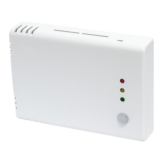
ROOM TRANSMITTER PRODUCT DESCRIPTION The RSMFH-3 series are multifunctional room transmitters which measure CO concentration levels, temperature, relative humidity and ambient light. They have three analogue / modulating outputs for temperature, relative humidity and CO 24 VDC power supply. Through Modbus RTU, all parameters are accessible. -
Page 5: Operational Diagrams
[%] rH [%] range range Analogue / modulating output 3 [%] [ppm] 5.000 range range T [°C] / rH [%] MIW-RSMFH-3-EN-000 - 15 / 12 / 2023 5 - 7 www.sentera.eu back to the table of contents... -
Page 6: Wiring And Connections
MOUNTING & OPERATING INSTRUCTIONS IN STEPS Before you start mounting the unit, read carefully “Safety and Precautions”. Choose a smooth surface for installation (a wall, panel, etc.). MIW-RSMFH-3-EN-000 - 15 / 12 / 2023 6 - 7 www.sentera.eu back to the table of contents... - Page 7 (not included). Mind the correct mounting position (Fig. 3) and unit dimensions (Fig. 2). Fig. 1 Snap-fits release Fig. 2 Mounting dimensions 59,8 104,5 104,5 MIW-RSMFH-3-EN-000 - 15 / 12 / 2023 7 - 7 www.sentera.eu back to the table of contents...
- Page 8 To assure correct communication, the NBT needs to be activated in only two devices on the Modbus RTU network. If necessary, enable the NBT resistor via 3SModbus or Sensistant (Holding register 9). MIW-RSMFH-3-EN-000 - 15 / 12 / 2023 8 - 11 www.sentera.eu...
-
Page 9: Operating Instructions
Alert 2 level (Fig. 5 - 3). Blinking red LED indicates loss of communication with a sensor (Fig. 5 - 3). MIW-RSMFH-3-EN-000 - 15 / 12 / 2023 9 - 11 www.sentera.eu back to the table of contents... -
Page 10: Verification Of Installation
Any alterations or adjustments to the product absolve the manufacturer of all liability. The manufacturer disclaims all liability for typographical or other errors in this document. MIW-RSMFH-3-EN-000 - 15 / 12 / 2023 10 - 11 www.sentera.eu... -
Page 11: Maintenance
In case of heavy pollution, clean with a non-aggressive product. In these circumstances the unit should be disconnected from the supply. Pay attention that no fluids enter the unit. Only reconnect it to the supply when it is completely dry. MIW-RSMFH-3-EN-000 - 15 / 12 / 2023 11 - 11 www.sentera.eu...
Need help?
Do you have a question about the RSMFH-3 and is the answer not in the manual?
Questions and answers