
Related Manuals for Sentera Controls DPD-F-1K0


Summary of Contents for Sentera Controls DPD-F-1K0
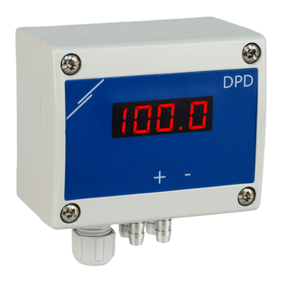
- Page 1 DUAL DIFFERENTIAL PRESSURE TRANSMITTER WITH DISPLAY Mounting and operating instructions...
-
Page 2: Table Of Contents
DUAL DIFFERENTIAL PRESSURE TRANSMITTER WITH DISPLAY Table of contents SAFETY AND PRECAUTIONS PRODUCT DESCRIPTION ARTICLE CODES INTENDED AREA OF USE TECHNICAL DATA STANDARDS OPERATIONAL DIAGRAM WIRING AND CONNECTIONS MOUNTING INSTRUCTIONS IN STEPS OPERATING INSTRUCTIONS VERIFICATION OF INSTALLATION TRANSPORT AND STORAGE WARRANTY AND RESTRICTIONS MAINTENANCE MIW-DPD-X-EN-001 - 09 / 04 / 2020... -
Page 3: Safety And Precautions
DUAL DIFFERENTIAL PRESSURE TRANSMITTER WITH DISPLAY SAFETY AND PRECAUTIONS Read all the information, the datasheet, the Modbus register map, the mounting and operating instructions and study the wiring and connection diagram before working with the product. For personal and equipment safety, and for optimum product performance, make sure you entirely understand the contents before installing, using, or maintaining this product.. -
Page 4: Product Description
(0—10 VDC / 0—20 mA / 0—100 % PWM). ARTICLE CODES Maximum power Nominal power Codes Power supply Imax Operating range consumption consumption DPD-F-1K0 0—1.000 Pa DPD-F-2K0 0—2.000 Pa 18—34 VDC 1,85 W 1,35 W 100 mA DPD-F-4K0 0—4.000 Pa DPD-F-10K 0—10.000 Pa... -
Page 5: Standards
DUAL DIFFERENTIAL PRESSURE TRANSMITTER WITH DISPLAY ■ Implemented K-factor ■ Selectable internal voltage source for PWM output: 3,3 or 12 VDC ■ Differential pressure, air volume or air velocity readout via Modbus RTU ■ Selectable minimum and maximum operating ranges ■... -
Page 6: Wiring And Connections
DUAL DIFFERENTIAL PRESSURE TRANSMITTER WITH DISPLAY WIRING AND CONNECTIONS Article type DPD-F DPD-G 18—34 VDC 18—34 VDC 13—26 VAC Ground Common ground AC ~ Ground / AC ~ Modbus RTU (RS485), signal A Modbus RTU (RS485), signal /B Analogue / modulating output 1 (0—10 VDC / 0—20 mA / PWM) Ground AO1 Common ground Analogue / modulating output 2 (0—10 VDC / 0—20 mA / PWM) - Page 7 DUAL DIFFERENTIAL PRESSURE TRANSMITTER WITH DISPLAY Fig. 3 Wiring and connections Switch on the power and perform a calibration procedure (refer to section “OPERATING INSTRUCTIONS”) . Connect the nozzles to the duct (see Fig. 4). Depending the application you must use a specific connection set to connect the nozzles of the unit to the duct: To measure differential pressure, use PSET-QF or PSET-PVC set (pressure measurement is the unit default setting);...
- Page 8 DUAL DIFFERENTIAL PRESSURE TRANSMITTER WITH DISPLAY Fig. 4 Connecting with accessories Application 1: Measuring differential pressure [Pa] or Application 2: Measuring volume flow [m³/h] or air velocity [m/s] volume flow [m³/h] using PSET-PVC using PSET-PT Sensor module 1 Sensor module 2 Connect the nozzles with the tubing.
-
Page 9: Operating Instructions
DUAL DIFFERENTIAL PRESSURE TRANSMITTER WITH DISPLAY Fig. 6 PWM (Open collector) connection example External pull-up resistor 50—100 kΩ External voltage PWM GND source (5—30 VDC) Optional settings To assure correct communication, the NBT needs to be activated in only two devices on the Modbus RTU network. - Page 10 DUAL DIFFERENTIAL PRESSURE TRANSMITTER WITH DISPLAY Sensor module 2: Disconnect the nozzles and make sure they are not clogged. There are two options for starting the calibration process: ■ Either write “1” in holding register 90 or press tact switch SW2 for about 5 seconds until the blue LED4 on the printed circuit board blinks twice and release it.
- Page 11 DUAL DIFFERENTIAL PRESSURE TRANSMITTER WITH DISPLAY Measurement readout enabled Value of holding register 61 / 81: Display mode: Differential pressure Volume flow rate Air velocity Фи Differential pressure display mode (see Fig. 9): The LED display shows the differential pressure with a resolution of 1 Pa. An example of displaying 1.000 Pa is given in Fig.
- Page 12 DUAL DIFFERENTIAL PRESSURE TRANSMITTER WITH DISPLAY Display indications The table below shows the display indications according to the measured parameter: Table 1 Display indications Parameter Differential pressure Volume flow Air velocity Sensor 1 Under the minimum range Sensor 2 Sensor 1 Above the maximum range Sensor 2...
-
Page 13: Verification Of Installation
DUAL DIFFERENTIAL PRESSURE TRANSMITTER WITH DISPLAY VERIFICATION OF INSTALLATION After switching on the power supply, the green ON/OFF LED on the printed circuit board must be on solid indicating that the unit is powered (Fig. 12 Operating indication). If the LED is OFF, check the connections. Blinking green RX and TX LEDs indicate that the unit has detected a Modbus network (Fig.
Need help?
Do you have a question about the DPD-F-1K0 and is the answer not in the manual?
Questions and answers