Table of Contents
Advertisement
Advertisement
Table of Contents

Subscribe to Our Youtube Channel
Related Manuals for Sentera Controls SPS series


Summary of Contents for Sentera Controls SPS series
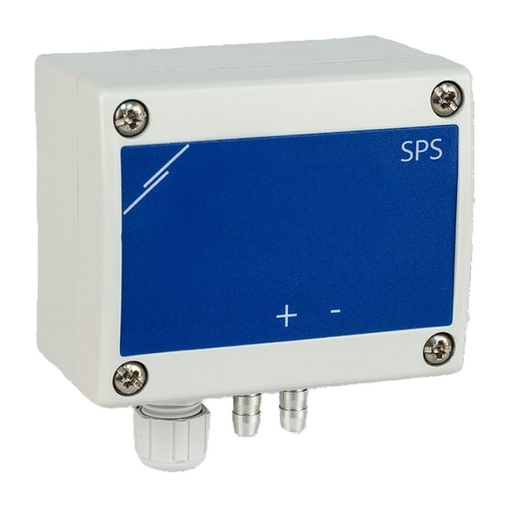
- Page 1 DIFFERENTIAL PRESSURE TRANSMITTER Mounting and operating instructions...
-
Page 2: Table Of Contents
DIFFERENTIAL PRESSURE TRANSMITTER Table of contents SAFETY AND PRECAUTIONS PRODUCT DESCRIPTION ARTICLE CODES INTENDED AREA OF USE TECHNICAL DATA STANDARDS OPERATIONAL DIAGRAM WIRING AND CONNECTIONS MOUNTING INSTRUCTIONS IN STEPS VERIFICATION OF INSTALLATION INSTRUCTIONS OPERATING INSTRUCTIONS MODBUS REGISTER MAPS TRANSPORT AND STORAGE WARRANTY AND RESTRICTIONS MAINTENANCE MIW-SPS-EN-001 - 29 / 11 / 2018... -
Page 3: Safety And Precautions
DIFFERENTIAL PRESSURE TRANSMITTER SAFETY AND PRECAUTIONS Read all the information, the datasheet, mounting and operating instructions and study the wiring and connection diagram before working with the product. For personal and equipment safety, and for optimum product performance, make sure you entirely understand the contents before installing, using, or maintaining this product. -
Page 4: Product Description
DIFFERENTIAL PRESSURE TRANSMITTER PRODUCT DESCRIPTION The SPS-2K0/6K0 is a compact multi-range differential pressure transmitter. It provides an analog / digital output and eight selectable measuring windows alongside with easy manual sensor calibration and Modbus register reset. ARTICLE CODES Code Supply Connection SPS-G-2K0 13—26 VAC... -
Page 5: Standards
DIFFERENTIAL PRESSURE TRANSMITTER STANDARDS ■ Low Voltage Directive 2014/35/EC ■ EMC Directive 2014/30/EC ■ WEEE Directive 2012/19/EU ■ RoHs Directive 2011/65/EU OPERATIONAL DIAGRAM 0 10 20 30 40 50 60 70 80 90 100 Output [%] WIRING AND CONNECTIONS Positive DC voltage / AC ~ Ground / AC ~ Modbus RTU (RS485) signal A Modbus RTU (RS485) signal /B... - Page 6 DIFFERENTIAL PRESSURE TRANSMITTER Fix the rear lid of the enclosure on the wall / panel by suitable fastening elements. Mind the correct mounting position and unit mounting dimensions. (See Fig. 1 Mounting dimensions and Fig. 2 Mounting position.) Fig. 1 Mounting dimensions Fig. 2 Mounting position Correct Incorrect Do the wiring according to the wiring diagram (see Fig. ...
- Page 7 DIFFERENTIAL PRESSURE TRANSMITTER Customise the factory settings to the desired ones: To select the analog output mode, use SW1 switch. (See Fig. 5 Analog output selection switch.) ► Select switch position 1 for 0—10 VDC mode of the analog output. ►...
-
Page 8: Verification Of Installation Instructions
DIFFERENTIAL PRESSURE TRANSMITTER VERIFICATION OF INSTALLATION INSTRUCTIONS When you switch on the unit the green LED (Fig 8 Power indication) should give out continuous green light. If it does, your unit is powered on. If this is not the case, check the connections again. - Page 9 DIFFERENTIAL PRESSURE TRANSMITTER Fig. 10 Sensor calibration and Fig. 11 Sensor calibration / Modbus register Modbus register reset tact switch reset / normal operation indication Reset of Modbus Registers procedure: Press button SW2 for 4 seconds until the blue LED on the printed circuit board (Fig. 11) blinks twice and keep pressing the button until it blinks three times.
- Page 10 DIFFERENTIAL PRESSURE TRANSMITTER To get correct calculation of the volume flow rate, the correct K‑factor of the NO T E fan / drive has to be written in holding register 17! ■ Input register 7 gives information about the current working range. In Standalone mode it contains the working range which is set by jumpers 1, 2 and 3.
-
Page 11: Modbus Register Maps
DIFFERENTIAL PRESSURE TRANSMITTER ■ Holding register 15 (40015) defines the minimum pressure limit. The default value is the minimum of the set range. When the measured pressure is below this value, input register 4 (“Min Pressure Limit Flag”) sets to '0', otherwise it is '1'. This register accepts values between -100 and 2.000. -
Page 12: Transport And Storage
DIFFERENTIAL PRESSURE TRANSMITTER HOLDING REGISTERS Data type Description Data Default Values Address unsigned int. Device address 1—247 9.600 Baud rate unsigned int. Modbus communication baud rate 19.200 38.400 Parity mode unsigned int. Parity check mode SPS-X-2K0 = 1015 Device type unsigned int.
Need help?
Do you have a question about the SPS series and is the answer not in the manual?
Questions and answers