
Subscribe to Our Youtube Channel
Related Manuals for Sentera Controls DSTHG-2


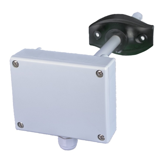
Summary of Contents for Sentera Controls DSTHG-2
- Page 1 DSTHX-2 COMBINED TEMPERATURE AND RELATIVE HUMIDITY DUCT TRANSMITTER Mounting and operating instructions...
-
Page 2: Table Of Contents
DSTHX-2 COMBINED T AND rH DUCT TRANSMITTER Table of contents SAFETY AND PRECAUTIONS PRODUCT DESCRIPTION ARTICLE CODES INTENDED AREA OF USE TECHNICAL DATA STANDARDS OPERATIONAL DIAGRAMS WIRING AND CONNECTIONS MOUNTING & OPERATING INSTRUCTIONS IN STEPS OPERATING INSTRUCTIONS MODBUS REGISTER MAPS VERIFICATION OF INSTALLATION INSTRUCTIONS TRANSPORT AND STORAGE WARRANTY AND RESTRICTIONS... -
Page 3: Safety And Precautions
DSTHX-2 COMBINED T AND rH DUCT TRANSMITTER SAFETY AND PRECAUTIONS Read all the information, the datasheet, mounting and operating instructions and study the wiring and connection diagram before working with the product. For personal and equipment safety, and for optimum product performance, make sure you entirely understand the contents before installing, using, or maintaining this product. -
Page 4: Product Description
Maximum power Nominal power Article code Supply Imax consumption consumption 18—34 VDC 1,68 W 1,26 W 70 mA DSTHG-2 15—24 VAC ±10% 1,8 W 1,35 W 75 mA DSTHF-2 18—34 VDC 1,68 W 1,26 W 70 mA INTENDED AREA OF USE... -
Page 5: Operational Diagrams
T [°C] rH [%] range range range range WIRING AND CONNECTIONS Article type DSTHF-2 DSTHG-2 18—34 VDC 18—34 VDC 15—24 VAC ±10% Ground Common ground AC ~ Modbus RTU (RS485), signal A Modbus RTU (RS485), signal A Modbus RTU (RS485), signal /B... -
Page 6: Mounting & Operating Instructions In Steps
DSTHX-2 COMBINED T AND rH DUCT TRANSMITTER MOUNTING & OPERATING INSTRUCTIONS IN STEPS Before you start mounting the DSTHX-2 duct transmitter, read carefully “Safety and Precautions”. Follow these steps: When preparing to mount the DSTHX-2, bear in mind that the unit itself must be installed onto the outer surface of the duct both via fixing the flexible flange or directly the unit enclosure, while the probe must be inserted inside the duct, see Fig. - Page 7 DSTHX-2 COMBINED T AND rH DUCT TRANSMITTER Having selected the appropriate mounting location, proceed with the following steps: Drill a Ø 13 mm hole into the duct and insert the probe. Apply an air-tight sealing between probe and duct. Fix the flange onto the duct outer surface using the self-drilling screws delivered with the unit.
-
Page 8: Operating Instructions
COMBINED T AND rH DUCT TRANSMITTER Fig. 4 Wiring and connections Supply voltage DSTHF-2: 18—34 VDC DSTHG-2: 18—34 VDC / 15—24 VAC ±10 % Modbus Analogue / modulating output 2 - rH (0—10 VDC / 0—20 mA / PWM) Analogue / modulating 1 - T (0—10 VDC / 0—20 mA / PWM) -
Page 9: Modbus Register Maps
0— 2 Modbus parity unsigned int Parity check mode 1 = 8E1 default: 1 2 = 8O1 DSTHG-2 = 1.632 Device type unsigned int Device type. Read only DSTHF-2 = 1.633 HW version unsigned int Hardware version of the device. Read only XXXX 0x0100 = HW version 1.0... -
Page 10: Verification Of Installation Instructions
DSTHX-2 COMBINED T AND rH DUCT TRANSMITTER HOLDING REGISTERS Holding Registers Data type Description Data Values Minimum value of relative humidity range, Minimum relative humidity 0—(Max-50) unsigned int cannot be set higher than maximum relative 200 = 20,0 % rH range default: 0 humidity range minus 5%...
Need help?
Do you have a question about the DSTHG-2 and is the answer not in the manual?
Questions and answers