
Related Manuals for SMC Networks JXD1-M Series


Summary of Contents for SMC Networks JXD1-M Series
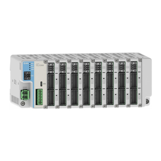
- Page 1 No. DOC1066918 PRODUCT NAME Manifold Controller for electric actuators MODEL / Series / Product Number JXD1-M...
- Page 2 Table of Contents 1. Safety Instructions 2. Outline of Product 2.1 Features 2.2 Product configuration 2.3 How to order 2.4 Accessories (1) Actuator cable (Common cable for actuator with/without lock) (2) CC-Link communication plug (3) Control power supply plug (4) Motor power supply plug (5) Power supply blocking plug 3.
- Page 3 3.5.2 Controller dimensions 3.6 Power supply 4. Start up procedure 4.1 Checking the package contents 4.1.1 Gateway unit 4.1.2 Driver unit 4.1.3 Options 4.2 Unit Connection 4.3 Assembling the controller 4.4 Wiring the controller 4.5 Connecting to the ACT-Connected software 4.6 Driver unit settings 4.6.1 Setting parameters 4.7 Gateway unit settings...
- Page 4 (2) Disconnecting the motor power supply plug 7.3 Details of power supply blocking plug 7.3.1 Power supply blocking plug specifications 7.3.2 Wire specifications for power supply blocking plug 7.3.3 Power supply blocking plug wiring (1) Wiring of power supply (M24VIN,M24VOUT) (2) Wiring of the stop switch (motor power supply disconnect) (3) Wiring for lock force release switch (LKRLS) 7.4 Wiring of stop circuits...
- Page 5 9.4.3 How to set the fieldbus operation mode 9.4.4 Data area of the PLC⇔Gateway Unit (1) Data area of PLC⇒Gateway Unit (2) Data area of Gateway Unit⇒PLC (3) Unset mode 9.4.5 Data assignment details for each operation mode (1) Common part of each mode (gateway control/response area) (2) Direct numerical setting mode (3) Step instruction mode (4) Simple direct value mode...
- Page 6 12.1.1 Overview of start-up procedures 12.1.2 Power-on 12.1.3 When an alarm (Group E) is cleared by reconnecting power 12.2 Operation Procedure of Indicated Operation Function by Step Data No. 12.2.1 Positioning operation (1) In [Step instruction mode], [IO mode], and [Simple direct value mode] (2) In [Direct numeric setting mode] 12.2.2 Pushing Operation (1) In [Step instruction mode], [IO mode], and [Simple direct value mode]...
- Page 7 JXD1-M/Controller 1. Safety Instructions These safety instructions are intended to prevent hazardous situations and/or equipment damage. These instructions indicate the level of potential hazard with the labels of “Caution,” “Warning” or “Danger.” They are all important notes for safety and must be followed in addition to International Standards (ISO/IEC) , and other safety regulations.
- Page 8 JXD1-M/Controller 1. Safety Instructions Caution We develop, design, and manufacture our products to be used for automatic control equipment, and provide them for peaceful use in a manufacturing industry. Use in non-manufacturing industries is not covered. Products SMC manufacture and sell cannot be used for the purpose of transactions or certification specified in the Measurement Act.
- Page 9 2. Outline of Product 2.1 Features Features of the controller. ●Up to 16 axes can be connected By connecting driver units, actuators for up to 16 axes can be connected and controlled. ●Easy registration of connected actuators The controller setup software "ACT-Connected" makes it easy to register initial settings for each actuator. Test operation and status monitoring are also available.
- Page 10 ●Area output function When the actuator position is within the position range specified by the step data "Area 1" and "Area 2," the memory corresponding to the area output signal of the host device turns ON. Caution Please keep this manual safe for future use. It will be necessary to refer to this manual along with the operation manuals for other electric actuators, controller setting software at installation and fault finding.
- Page 11 2.2 Product configuration Manifold Controller Driver Unit Termination Unit JXD1-MDP□ JXD1-MTR Gateway Unit Connects up to 8 units JXD1-MGW-CC-□ CC-Link (Prepared by the user) Leads Cables to CC-Link communication plug to CHA, CHB Straight type LEC-CMJ-S T-branch type JX-NT-M JXD1-MGW-EN-□ Power supply blocking EtherNet/IP plug...
- Page 12 2.3 How to order Describes how to indicate the type and number of units to make up the Manifold Controller. Termination Unit Gateway Unit Driver Unit ■Gateway Unit J X D 1 – M G W – □□–□ □ □ □ ommunication Protocol Termination Option CC-Link...
- Page 13 2.4 Accessories Describes the accessories available. (1) Actuator cable (Common cable for actuator with/without lock) JX – CP – D – □ Cable length (L) Cable length(L) 1.5 m 8 mm 10 m 15 m 11 mm 20 m ...
- Page 14 (3) Control power supply plug JX-NC-M Name Function Details Not used Wiring prohibited Control power C24V (+) side of control power supply supply (+) Grounding terminal. Frame Ground ① ② Connection terminal for external stop circuit for all-axes. When 24 VDC is input, stop of all axes is Release lock (+) ④...
- Page 15 3. Specifications 3.1 Specifications 3.1.1 Basic product specifications Item Specifications Power supply voltage 24 VDC ±10% Determined by unit configuration, actuator type and number of axes 1) connected Current consumption (refer to the "Electric Actuator Selection Software" on the SMC website) Number of control axes 16 axes maximum (max.
- Page 16 (2) Gateway Unit specifications (EtherNet/IP) Item Specifications Type JXD1-MGW-EN-□ Control power current consumption (gateway unit Less than 350 [mA] only) 3) Protocol EtherNet/IP™ Applicable Volume1 (Edition3.34), system 1) Version Volume2 (Volume1.32) Communication speed 10/100 [Mbps] (Auto-negotiation) Communication 2) EDS file Configuration file Input / Output :18 bytes ~...
- Page 17 3.2 Gateway Unit 3.2.1 Details (1) CC-Link ① ⑥ ② ③ ⑦ ⑤ ③ ② ④ Display Name Details Indicates Power-on and EEPROM write status Indicates Controller alarm status LRUN Indicates CC-Link communication status LERR Indicates CC-Link error status. Control power supply connector Connector for the controller power supply.
- Page 18 (2) EtherNet/IP ① ⑥ ② ⑦ ⑤ ③ ④ Display Name Details Indicates Power-on and EEPROM write status Indicates Controller alarm status Indicates EtherNet/IP controller status. Indicates EtherNet/IP communication status. Control power supply connector Connector for the controller power supply. Motor power supply connector Connector for the power supply of the actuator.
- Page 19 3.2.2 External Connections (1) Control power supply connector Connect using the plug supplied. Control power supply plug Gateway Unit (accessory) Controller input JX-NC-M power supply (The electrical wires and controller input power supply are provided by the user). For more information, refer to section 7.1 Details of control power supply plug.
- Page 20 (4) CC-Link communication connector Gateway Unit CC-Link dedicated Communication cable (The PLC and Communication cable should be provided by the user). For more information, refer to section 7.5 Details of CC-Link communication plug . (5) EtherNet/IP communication connector EtherNet/IP dedicated Communication cable (The PLC and Communication cable should be provided by the user).
- Page 21 3.3 Driver Unit 3.3.1 Details ⑤ ・1 axis ・2 axes ④ ④ ① ① ② ② ⑥ ③ Display Name Details LED for status indication. CH A LED (Red / Green) A single two-colour LED indicates the servo motor is ON CH B (green) and ALARM (red).
- Page 22 3.3.2 External Connections (1) Motor power supply blocking connector Motor power supply blocking connector (accessory) Driver Unit JX-NL-M Controller input power supply For more information, refer to section 7.3 Details of power supply blocking plug. (2) Motor / Encoder connector Connect the controller and actuator using an actuator cable JX-CP-D-□.
- Page 23 3.4 Termination Unit ① ② Display Name Details Connector for unit-to-unit connection Connectors between units. Nameplate A nameplate label with product information. -23- No. DOC1066918...
- Page 24 3.5 Outline dimensions dimensions 3.5.1 Unit (1) Gateway Unit ●Direct mounting EtherNet/IP CC-Link ● DIN rail mounting EtherNet/IP CC-Link -24- No. DOC1066918...
- Page 25 (2) Driver Unit 1 axis 2 axes (3) Termination Unit ●Direct mounting ●DIN rail mounting -25- No. DOC1066918...
- Page 26 3.5.2 Controller dimensions ●Direct mounting ●DIN rail mounting Number of Driver Units L [mm] 88.1 109.7 131.3 152.9 174.5 196.1 217.7 239.3 A [mm] 100.3 121.9 143.5 165.1 186.5 208.3 229.9 251.5 B [mm] 109.9 131.5 153.1 174.7 196.3 217.9 239.5 261.1 3.6 Power supply...
- Page 27 4. Start up procedure Install, wire, set and operate the controller referring to the procedure below when the product is used for the first time. 4.1 Checking the package contents After unpacking everything, check the description on the label to identify the controller and the number of accessories.
- Page 28 4.1.3 Options Product name 1 DIN rail mounting bracket (JX-DR-M) 1 Direct mounting bracket (JX-SC-M) Control power supply plug (JX-NC-M) Motor power supply plug (JX-NM-M) Power supply blocking plug (JX-NL-M) Straight type communication plug for CC-Link (LEC-CMJ-S) T branch type communication plug for CC-Link (JX-NM-M) Actuator cable (JX-CP-D-□) Termination Unit (JXD1-MTR) ...
- Page 29 4.7 Gateway unit settings 4.7.1 Setting parameters Set the parameters of the gateway unit. See below for information on setting parameters for each communication protocol. ●For CC-Link: section 9.2.1 Controller parameter setting ●For EtherNet/IP: section 9.3.1 Controller parameter setting 4.7.2 PLC settings Set the PLC parameters.
- Page 30 5. Unit Connection 5.1 Overview This controller must comprise of three different units, a gateway unit, driver unit and termination unit. The method of unit connection is identical regardless of the type of unit. The configuration of the units in the controller is as follows. 1) Up to 8 driver units maximum.
- Page 31 5.2 Connection Method This controller connects units together in the same way, regardless of the type of unit. The following is an example of a unit-to-unit connection when connecting a gateway unit ⇔ driver unit. (1) After checking that the unit connection screws (2 places) are up, connect the units together while aligning the connectors.
- Page 32 6. Mounting 6.1 Mounting The controller can be Direct mounted using screws or mounted on a DIN rail. Details of the controller mounting options are shown below. 6.1.1 DIN rail mounting Attach DIN rail mounting brackets to the rear of the Gateway unit and the Termination unit so that the controller can be mounted on a DIN rail.
- Page 33 6.1.2 Direct mounting Attach the direct mounting brackets to the rear of the Gateway unit and the Termination unit so that the controller can be mounted directly to a panel or similar using screws. When DIN-rail mounting this product, be sure to use the screws supplied. Attach the direct mounting brackets to the gateway unit and termination unit using four M4×10L Tapping Screws.
- Page 34 6.3 Mounting location Design the size and mounting location of the control cabinet so that it is within the operating temperature range of the controller. Mount this controller vertically on the wall as follows: 1) In the vertical direction, provide sufficient clearance from other equipment and wiring ducts in order to secure ventilation space.
- Page 35 7. Wiring 7.1 Details of control power supply plug supply 7.1.1 Control power plug specifications The specifications of the control power supply plug supplied with the controller are shown below. supply Control power plug Pin No. Terminal Function Functional explanation Not used Wiring prohibited Control...
- Page 36 Wiring of power supply (C24V) Connect the (+) side of the controller input power supply 24 VDC to the C24V terminal of the control power supply plug. ■Open/close lever Press the open/close lever with a dedicated screwdriver and insert the wire into the wire entry.
- Page 37 7.2 Details of motor power supply plug 7.2.1 Motor power supply plug specifications The specifications of the motor power supply plug supplied with the controller are shown below. Motor power supply Pin No. Terminal Function Functional explanation plug Negative common power supply. M24V terminal / C24V terminal / Common power EMG terminal (Control power supply...
- Page 38 Wiring of power supply (M24V, 0V) The motor power supply plug is connected to the controller power supply 24 VDC. The M24V connects to the (+) side of the controller power supply. The 0V connects to the (-) side of the controller power supply. ■Open/close lever Press the open/close lever with a dedicated screwdriver and insert the wire into the wire entry.
- Page 39 7.3.2 Wire specifications for Power supply blocking plug Prepare the wiring according to the following specifications (to be prepared by the user). Item Specifications Single, stranded wire → AWG 22 ~ 20 (0.3 ~ 0.5 mm Applicable wire size The rated temperature of the insulation coating should be 60 °C or more. Stripped wire length Φ2.5 mm or less 10 mm...
- Page 40 (3) Wiring for lock force release switch (LKRLS) The controller has Short Brake Function, which makes it difficult for the actuator mover to move while the control input power supply (C24V) is being supplied. If the electric actuator mover is intentionally moved by external force (e.g.
- Page 41 7.4 Wiring of stop circuits This controller is designed to stop the actuator operation using the following method. ●Operation stops after deceleration of all axes due to the control power supply plug EMG terminal and the disconnect of the controller power supply 24 VDC. ●Operation stops after deceleration for each axis by turning off between M24VIN1 and M24VOUT1 (For CH A) and between M24VIN2 and M24VOUT2 (For CH B) of the power supply blocking plug.
- Page 42 Caution (1) When the Control power supply plug is disconnected between the EMG terminal and the controller power supply 24VDC, the actuator stops at the maximum deceleration for all axes. All actuators will then be in a servo-off state and "ESTOP" signal will turn ON. For more information on "ESTOP"signal. Please see 9.4.5 Data assignment details.
- Page 43 (3) Shutdown of motor power supply (relay contact (2)) If external operation is required to disconnect the motor power supply, connect a relay contact (24 VDC, contact capacity 5 A minimum) between M24VIN1 and M24VOUT1(For CH A) and between M24VIN2 and M24VOUT2 (For CH B) on the power supply blocking plug.
- Page 44 7.5 Details of CC-Link communication plug 7.5.1 Specifications of CC-Link communication plug The communication plug connector specification is shown below. Straight type T-branch type LEC-CMJ-S JX-NT-M Designation Description Frame Ground CC-Link shield CC-Link Ground line CC-Link communication line B CC-Link communication line A In the CC-Link system, a terminating resistor is connected between terminals 4 and 5.
- Page 45 7.5.2 Wire specifications for CC-Link communication plug Specifications Item Applicable wire size AWG 24 to 12 (0.2 to 2.5 mm (Single line, stranded wire) The rated temperature for the insulation coating: 60 C or more Straight type:7 mm Stripped section length T-branch type:10 mm 7.5.3 Wiring for CC-Link communication plug Wire the CC-Link communication line to the communication plug and insert it into the communication...
- Page 46 8. LED display details 8.1 Gateway Unit (CC-Link) This product can be operated using either the step number instruction method, which selects pre-set data to instruct the operation, or the numerical instruction method, which directly changes parameters on the pre-set step data number.
- Page 47 8.2 Gateway unit (EtherNet/IP) 8.2.1 LED display contents Details of the LED indications are shown below. LED Name Contents Power not supplied Indicates power-on status and EEPROM Green light ON Power supplied writing status. Flashing green Writing to EEPROM in progress. Normal operation Indicates an alarm condition on the gateway unit.
- Page 48 8.3 Driver units 8.3.1 LED display details Details of the LED indications are shown below. LED Name Contents CH A Axis 1 servo ON / alarm LED CH B Axis 2 servo ON / alarm LED 8.3.2 Driver unit status and LED indications The driver unit status and LED indications are shown below.
- Page 49 9. Configuration of Gateway unit 9.1 List of Gateway unit special setting parameters Please use the ACT-Connected software to set the gateway unit special setting parameters. Name Contents Enable / disable PLC commands It is possible to select the use of the GWMON signal, which operates the enable / disable of commands from a PLC or other higher-level communication device to the gateway unit.
- Page 50 (3) Parameters automatically calculated by ACT-Connected The number of occupied stations, the number of extended cycles and the CC-Link version depend on the data length. The data length is indicated by a combination of the number of connected axes and the operating mode of each axis.
- Page 51 9.2.2 Setting PLC parameters Configure the PLC settings. Use a PLC compatible with CC-Link Ver. 1.10 or Ver. 2.00. The following is an example of a setting when using a Mitsubishi CC-Link system master and local unit (Q series). PC series: QCPU (Q mode) PC type: Q00UJ First address of remote I/O (Rx, Ry), remote registers (RWr, RWw), etc.
- Page 52 9.3 Gateway units (EtherNet/IP) 9.3.1 Controller parameter setting The controller parameters are set using the ACT-Connected software. (4), (5) (1), (2), (3) The settings for each parameter are given below. (1) IP address Set the IP address within the range 0.0.0.0 to 255.255.255.255. When the IP address is set to 0.0.0.0, the IP address is obtained from a DHCP server.
- Page 53 ・Right-click on the selection [Ethernet] in the [I/O Configuration] folder, and select [New Module]. ・The [Select Module Type] screen is displayed. Select [Generic Ethernet Module] and select [Create]. ・The [Module Properties] screen is displayed, to perform setup. (1) Name: Enter the required unit name. (2) Select the data format of Comm: Connection Parameters.
- Page 54 9.4 Fieldbus Operation Mode Settings (Fieldbus common settings) 9.4.1 Outline of Fieldbus Operation Mode This mode transmits operation commands from the PLC to each axis unit of the controller via fieldbus (CC-Link, Ethernet/IP). Status signals and information from each axis unit are sent to the host PLC via fieldbus. 9.4.2 List of fieldbus operation modes The controller supports the following 4 patterns of fieldbus operation modes (hereinafter referred to as "operation modes").
- Page 55 9.4.3 How to set the fieldbus operation mode Using the controller setting software "ACT-Connected", the operation mode can be set from a PC. The factory default of the operating mode is " Unset mode ". For details, please refer to the ACT-Connected manual. 9.4.4 Data area of the PLC⇔Gateway Unit This section describes the contents of operation data communicated via fieldbus.
- Page 56 (1) Data area of PLC⇒Gateway Unit Assuming that 16 axes are connected and all axes are in the same operation mode, the data area assignment for each operation mode is described below. For CC-Link, the Gateway control area is assigned to Remote Output (Ry) and the connected axis control area to Remote Register (RWw).
- Page 57 (2) Data area of Gateway Unit⇒PLC Assuming that 16 axes are connected and all axes are in the same operation mode, the data area assignment for each operation mode is described below. For CC-Link, the gateway response area is assigned to the remote input (Rx) and the connection axis response area to the remote register (RWr).
- Page 58 (3) Unset mode This section explains the changes in data allocation when using the Unset mode, using the state in which two driver units of 2-axis specifications are connected as an example. Controller Axis Port Axis Setting CH A Enable Driver Unit 1 CH B...
- Page 59 9.4.5 Data assignment details for each operation mode Details of operation data are described for each mode. For the connected axis memory addresses, relative addresses are listed because they change depending on the connection status (axis No., number of connected axes, operation mode, etc.). (First address = n) (1) Common part of each mode (gateway control / response area) ●PLC⇒Gateway Unit (Gateway control area)
- Page 60 (2) Direct numerical setting mode ●PLC⇒Gateway Unit (Connected axis control area) PLC memory address Ether Name Details Link Net/IP 0~7 Lowermost Enter the target position as a 32-bit signed integer. 8~15 ↑ Target (Unit: 0.01 mm) 0~7 position ↓ The range of values is the same as the input range for “Position” in 10.3.1 Step Data Entry.
- Page 61 ●Gateway Unit⇒PLC (Connected axis response area) PLC memory address Ether Name Details Link Net/IP 0~7 Lowermost 8~15 Current ↑ Outputs the current position as a 32-bit signed integer. 0~7 Position ↓ (Unit: 0.01 mm) 8~15 Uppermost 0~7 Lower Current Outputs the Current force as a 16-bit signed integer. Upper 8~15 force...
- Page 62 (3) Step instruction mode ●PLC⇒Gateway Unit (Connected axis control area) PLC memory address Ether Name Details Link Net/IP 0~15 Not used 0~15 Not used Specifies the step data No. of operation data. Command Operation of the specified step data No. starts at the rising edge step data of the DRIVE signal.
- Page 63 ●Gateway Unit⇒PLC(Connection axis response area) PLC memory address Name Details Ether Link Net/IP 0~7 Lowermost 8~15 ↑ Current Outputs the current position as a 32-bit signed integer. (Unit: 0.01 mm) Position 0~7 ↓ 8~15 Uppermost OUT0 OUT1 Completed OUT2 Outputs the step data No. (0 to 63) for which the operation Step Data has been completed.
- Page 64 (4) Simple direct value mode ●PLC⇒Gateway Unit (Connected axis control area) PLC memory address Name Details Ether Link Net/IP 0~7 Lowermost ↑ 8~15 Target Enter the target position as a 32-bit signed integer. position (Unit: 0.01 mm) 0~7 ↓ 8~15 Uppermost Specifies the step data No.
- Page 65 ●Gateway Unit⇒PLC(Connected axis response area) PLC memory address Ether Name Details Link Net/IP 0~7 Lowermost 8~15 Current ↑ Outputs the current position as a 32-bit signed integer. 0~7 Position ↓ (Unit: 0.01 mm) 8~15 Uppermost OUT0 OUT1 Completed OUT2 Outputs the step data No. (0 to 63) for which the operation has been Step Data completed.
- Page 66 (5) IO mode ●PLC⇒Gateway Unit (Connected axis control area) PLC memory address Name Details Ether Link Net/IP Specifies the step data No. of operation data. Operation of the specified step data No. starts at the rising Command edge of the DRIVE signal. step data Only the lower 6 bits are valid (No.
- Page 67 ●Gateway Unit⇒PLC (Connected axis response area) PLC memory address Name Details Ether Link Net/IP OUT0 OUT1 OUT2 Outputs the step data No. (0 to 63) for which the move has been OUT3 completed. Completed OUT4 Step Data OUT5 Not used Indicates an alarm (warning) that is not accompanied by a stop.
- Page 68 9.5 Handling of Each Transmitted and Received Data 9.5.1 Handling of data Assuming that the operation mode is Direct numerical setting mode, this section describes the handling of operation data. ・1 word data For 1-word data such as speed, acceleration / deceleration, alarm code etc., handle as follows. 1)Example: When 100 mm/s is input for speed (Word n+4) (PLC ⇒...
- Page 69 9.5.2 Relationship between binary (BIN), decimal (OCT), and hexadecimal (HEX) The relationship between binary (BIN) / decimal (OCT) / hexadecimal (HEX) is as follows: binary decimal hexadecimal e.g.) 1 byte (HEX) (BIN) (OCT) -69- No. DOC1066918...
- Page 70 9.6 Controller input signal response time The controller input signal response time delay includes the following factors. (1) Controller input signal scan delay (2) Delay due to input signal analysis (3) Delay of command analysis When the signals are continuously input, set the time to more than twice the communication cycle time for the interval between signals, as the PLC processing delays and controller scanning delays can occur.
- Page 71 10. Driver unit settings 10.1 Parameter input for connected actuators 10.1.1 When using an actuator for the first time or to initialize the actuator parameters This command initializes (resets) the parameters set in the controller to the defaults. The settings are made in the "Write default value" section of the setup using the ACT-Connected software. The controller reads the connected actuator part number for each axis when checking the connection.
- Page 72 E.g.) Step data on the PC (ACT-Connected) screen Pushing Pushing Trigger Moving Movement Speed Acceleration Deceleration Position AREA 1 AREA 2 speed force force position mode [mm/s] [mm] [mm/s2] [mm/s2] [mm] [mm] [mm/s] [mm] 0(Posn) Absolute 20.00 1000 1000 18.00 22.50 1(Push) Absolute...
- Page 73 Description Range Explanation ■Effective only for the pushing operation (when the value for the "Pushing force" is from 1 to 100). 1 2 This defines the movement speed during the pushing operation. The lower limit is If this Speed is too high, it may cause damage to the actuator or work piece due to impacts.
- Page 74 10.3.2 Parameter Entry (1) Basic parameters The "Basic parameter" is the data to define the operating conditions, conditions of the actuator, etc. Details of basic parameters Activation: “XX” = Become effective just after it is recorded into the controller Description Range Details Activation...
- Page 75 (2) Return to origin parameters The “Return to origin parameters” is the setting data for the return to origin operation. Details of return to origin parameters Activation: “XX” = Become effective just after it is recorded into the controller “X” = Become effective after restarting the controller Description Range Details...
- Page 76 Description Range Details Activation An alarm will occur if the return-to-origin is not completed Origin return error 1~65535 within this time. If the return-to-origin speed is lowered, set time it according to the speed. (Unit: s) This defines the range to activate the INP output after the 1 2 Def In position return to origin operation.
- Page 77 (3) Drive parameters The "Drive parameters" is data to set the actuator motion and JOG operation. Details of drive parameters Activation: “XX” = Become effective just after it is recorded into the controller Description Range Details Activation Sets the level of followability of acceleration/deceleration. Followability to the acceleration becomes loose as the setting Acceleration and 1 2...
- Page 78 Activation Description Range Details Sets the speed loop P constant. (Unit: 10Hz) Caution Speed loop P Actuator causes unexpected behaviour when this 1 2 constant parameter setting is changed, which may result in equipment failure. To change the setting, please refer to the actuator manual.
- Page 79 11. Operation Explanation 11.1 Return to origin A Return to origin operation should be performed first in the following cases. (1) When the power is turned on. When power is turned on for the first time, homing is required. The next time the power is turned on again, homing is not required. (2) When the actuator or motor is replaced.
- Page 80 11.2 Positioning operation ■ Step instruction mode, IO mode Step data "Pushing force" is set to 0. The actuator moves to the target position specified by the step data "Position". ■ Simple direct value mode Step data "Pushing force" is set to 0. The actuator moves to the "Target position"...
- Page 81 11.3 Pushing operation ■Step instruction mode, IO mode The pushing operation is active when the value of the "Pushing force" in the Step data is set to "1" or more. The positioning operation is performed at the "Position" and "Speed" of the step data. Then, the pushing operation starts from the starting position defined by the "Position".
- Page 82 (1) Pushing operation is successfully performed ■Simple direct value mode, Step instruction mode, IO mode During the pushing operation, When the pushing force is higher than the value specified by "Trigger LV" of the step data for a certain time, “INP” will turn ON. Even after the completion of the pushing operation, the actuator will keep generating the force set in the step data.
- Page 83 (3) Movement of the workpiece after the completion of the pushing process [1] The workpiece moves in the pushing direction After the pushing operation is completed, the INP output turns off under the following conditions and follows the change within the positioning range. ■Simple direct value mode, Step instruction mode, IO mode: The thrust falls below the "Trigger LV"...
- Page 84 11.4 Methods of interrupting operation The following are methods of interrupting operation and stopping the actuator during positioning operation and pushing operation. The state after the interruption is different, therefore use the method appropriate to the application. ●Operation stops after deceleration of all axes by shut off between control power supply plug EMG terminal and controller power supply 24 VDC When connection between the control power supply plug EMG terminal and the controller power supply 24 VDC is disconnected during operation, the actuator will decelerate to a stop in all axes and then turn the...
- Page 85 11.5 Operation (example) 11.5.1 Positioning operation E.g.) Move an actuator from the origin to 100 mm point at 50 mm/s (Step No.1 instruction). Next, move the actuator from the 50 mm point to 100 mm point by moving it 5 times continuously, 10 mm at a time, at a speed of 50 mm/s (Step No.
- Page 86 E.g.) Move an actuator from the origin to 100 mm point at 50 mm/s (PLC No.1 instruction). Next, move the actuator from the 50 mm point to 100 mm point by moving it 5 times continuously, 10 mm at a time, at a speed of 50 mm/s (PLC No.2 instruction). ■...
- Page 87 11.5.2 Pushing Operation E.g.) Move the actuator from the origin to a point 100 mm away at 100 mm/s (Step Data No.1 is used for this operation). From the 100 mm point, the actuator must start a pushing operation of 10 mm/s speed and 50% or less force (the pushing distance is up to 5 mm).
- Page 88 E.g.) From the origin position, the machine moves to the 100 mm position at a speed of 100 mm/s. From the 100 mm position, a push operation is performed at a speed of 10 mm/s with a push thrust value of 50% or less (Maximum push-in amount is 5 mm) (PLC No.1 instruction).
- Page 89 12. Operating Procedure 12.1 Power start-up procedure 12.1.1 Overview of start-up procedures Procedure for start-up of the battery-less absolute encoder for every occasion when the power is supplied. (1) When power is supplied for the first time In the following cases, alarm code 153 [ ] will occur after Absolute encoder ID does not match controller data power-on.
- Page 90 12.1.2 Power-on -Procedure- ① Supply power ↓ Power ②ESTOP output is turned OFF ALARM output is turned OFF GWMON ↓ ③GWRUN output turns ON Input SVON Signals ↓ ④GWMON input is turned ON SETUP The GWMON input must only be turned ON if the setting "Enable/Disable PLC commands"...
- Page 91 12.1.3 When an alarm (Group E) is cleared by reconnecting power It is necessary to perform the Return to origin when alarm (group E) is generated and the alarm is cleared by turning off the power supply. When the power is supplied again after changing the Return to origin parameter “Return to Origin Direction” or “Zero positioning distance”, follow the same start up procedure.
- Page 92 12.2 Operation Procedure of Indicated Operation Function by Step Data No. Please refer to the following steps and timing charts for each item. 12.2.1 Positioning operation (1) In [Step instruction mode], [IO mode], and [Simple direct value mode] -Procedure- ①Input of step data No. (IN0 to IN5) For [simplified direct value mode], only the Input of Step Reading of Step...
- Page 93 (2) In [Direct numerical setting mode] -Example- Move the actuator directly to a position 50.00 [mm] from the origin at a speed of 100 mm/s using the direct numerical setting mode. An example of PLC settings is shown below. PLC Setting Example Target position In position Speed...
- Page 94 12.2.2 Pushing Operation (1) In [Step instruction mode]、[IO mode]、[Simple direct value mode] -Procedure- Timing chart / Pushing operation ①Input of step data No. (IN0 to IN5 Input) In the case of [simple direct value mode], the Reading of Step Input of Step data No.
- Page 95 (2) In [Direct numerical setting mode] -Example- The actuator is moved directly from the origin to a position of 100.00 [mm] at a speed of 100 [mm/s] in the From the 100.00 [mm] position, a pushing operation is performed at a Direct numerical setting mode.
- Page 96 12.2.3 Pause (HOLD) -Procedure- ①In operation (BUSY output turns ON) Turn ON the HOLD input. ↓ ②BUSY output turns OFF (It stops). ↓ ③Turn HOLD output OFF. ↓ ④BUSY output turns ON (It operates again). 12.2.4 Reset for operation -Procedure- ①In operation (BUSY output turns ON).
- Page 97 12.2.7 Area Output In [Step instruction mode]、[IO mode]、[Simple direct value mode] -Procedure- ●Step data No. 1 operation ①Input of step data No. (IN0 to IN5 input) In [Simple direct value mode], The PLC sets the "target position" without using step data only for the target position.
- Page 98 13. Alarm 13.1 Alarm detection of Gateway Unit 13.1.1 Alarms common to gateway units This section describes alarms generated by gateway units independent of the fieldbus communication protocol. (1) Unit/LED status and priority The LED indications for the Gateway Unit status are shown in the table below. LED Status Unit Status System error has occurred...
- Page 99 <Contents> This alarm occurs when the internal memory data of the gateway or Parameter Checksum abnormal driver unit is corrupted. (129) <Countermeasures> Please reconnect the power supply or replace the Gateway Unit. <Contents> Fieldbus This alarm occurs when a fieldbus module has failed. Module error <Countermeasures>...
- Page 100 <Contents> Ethernet initialization This alarm occurs when the initialization of the Ethernet circuit ends process abnormally or has failed. Error <Countermeasures> (240) Reconnect the power supply or replace the Gateway unit. <Contents> This alarm occurs when the CPU in the Gateway unit has detected an CPU error error.
- Page 101 13.1.2 Fieldbus specific alarms This section describes the alarms that may occur at the Gateway unit, which vary depending on the fieldbus communication protocol. (1) Alarm details and countermeasures for CC-Link communication The contents of alarms related to CC-Link communication can be checked on the LED display of the Gateway unit.
- Page 102 (2) Alarm details and countermeasures for Ethernet/IP communication The following table shows the alarms that can be checked on the controller LED display and their countermeasures. LED Names and Indications Controller Contents, measures Status <Contents> A configuration error has occurred. <Countermeasures>...
- Page 103 13.2 Alarm detection of driver unit The contents of alarms related to the driver unit can be checked using ACT-Connected. For details on how to check alarms, please refer to the ACT-Connected instruction manual. Caution When an alarm is generated, deactivate the alarm after troubleshooting and correcting the error with reference to section "(2) Alarms and countermeasures of the driver unit".
- Page 104 Alarm Name in How to ACT-Connected Group Contents, measures deactivate 1 (code) <Contents> The operation data is incorrect for the following conditions: (Settable range) (1) Area1 < Area2 (If both Area 1 and Area 2 are 0, the alarm does not occur). (2) Trigger LV ≤...
- Page 105 <Contents> Return to ORIG Return to origin is not completed within the set time. was not <Countermeasures> completed in RESET Make sure that there are no obstructions that interfere with the actuator the set time movement. (097) <Contents> The return to origin operation, positioning operation, pushing operation or Drive is ON JOG operation is requested while the Servo motor is OFF (when the EMG when SVRE is...
- Page 106 <Contents> This alarm is generated when the motor power-supply voltage, detected by the controller, is outside of the specified range. The controller checks the lower limit of the motor power supply voltage only when the servo ON is indicated. <Countermeasures> Make sure that the voltage supplied to the motor power (M24V) of the controller is within specification.
- Page 107 <Contents> The target The actuator failed to reach the set position within the set time limit. position was not RESET <Countermeasures> reached within SVON Make sure there are no obstructions that interfere with the actuator the set time limit movement. Also, make sure that the load, speed, acceleration and (149) deceleration are within the range of the actuator.
- Page 108 <Contents> An EEPROM error has occurred, or the number of writes has been exceeded. Turn OFF Caution and ON Memory When PWR (green) is flashing (EEPROM writing in progress), do not Abnormality the power turn off the controller power supply or disconnect the USB cable. has occurred supply for (197)
- Page 109 13.3 Predictive maintenance function The ACT-Connected software allows monitoring of Records relating to predictive maintenance functions ("Cumulative values" and "Estimated life of the electrolytic capacitors for the motor drive of the driver unit" shown below). This allows the maintenance timing to be set and checked. If the accumulated value exceeds the set number of times and distance, or when the estimated life of the electrolytic capacitor for the motor drive falls below 30% remaining, a warning (ALML) turns ON.
- Page 110 14. Precautions 14.1 Precautions for wiring and cables Warning (1) Adjusting, mounting or wiring changes should never be made before first turning OFF the power supply to the product. Electric shock, malfunction and damage can result. (2) Do not disassemble the cables. Use only specified cables. (3) Do not connect or disconnect the cable or connector with the power on.
- Page 111 14.2 Controller and Peripheral Devices / Specific Product Precautions Design and selection 14.2.1 Warning (1) Use the specified voltage. Otherwise, malfunction and damage to the controller may result. If the applied voltage is lower than the specified voltage, it is possible that the load cannot be moved due to an internal voltage drop.
- Page 112 (11) Do not install the product in an environment where flammable gas, explosive or corrosive gas, liquids or other substances are present. It could lead to fire, explosion and corrosion. (12) Avoid radiant heat from large heat sources such as direct sunlight or hot furnaces. It will cause failure of the controller or its peripheral devices.
- Page 113 14.2.4 Mounting Warning (1) The controller and its peripheral devices should be installed on a fire-proof material. Direct installation on or near a flammable material may cause fire. (2) Do not install this product in a location subject to vibration and impact. A failure and malfunction can result.
- Page 114 14.2.6 Power supply Caution Use a power supply with low noise between lines and between power and ground. In cases where noise is high, use an isolation transformer. (2) Use a power supply unit other than the inrush current suppression type for the 24 VDC controller input power supply.
- Page 115 15. Troubleshooting In case of any problems, please consult the following table. Consider replacing the controller if none of the causes on this table are applicable. It is possible that the product may be damaged due to the operating conditions (applications). Please contact SMC to discuss appropriate measures.
- Page 116 Investigation method Problem Problem Possible causes Countermeasures possible causes Check the voltage and current supplied to Is PWR (green) turned the controller. Power fault on or flashing? Or is ⇒3. Specifications ALM (red) turned on? ⇒7. Wiring Check if the wiring is connected correctly or if there is a broken wire or short-circuit The Controller by referring to this Operation Manual.
- Page 117 Is there a release sound If there is no sound of lock release, from the lock when the the lock brake may be broken. Lock release error lock forced release switch If the problem persists, please contact is turned on and off? SMC.
- Page 118 Refer to this instruction manual to check the wiring and check for disconnections or shorts. Correct the wiring as necessary and confirm that the input/output of each Has the condition of the signal is correct. Contact failure ⇒7. Wiring wiring been checked? ⇒9.4 Fieldbus Operation Mode Settings (Fieldbus common settings)
- Page 119 Check if there is equipment which Refer to the instruction manual of the generates a magnetic Influence of a electric actuator and keep equipment force, such as a magnet magnetic force that generates a magnetic force away or electro-magnetic coil from the motor.
- Page 120 Take appropriate measures according Check the timing of the to the contents of this manual. Signal timing signal from the PLC to ⇒9.6 Controller input signal the controller. response time During data writing (LED of driver unit CH A or CH B is flashing (cycle 400 The actuator ms)), the following actions may fix the does not move...
- Page 121 16.Definitions and terminology The major terminology used in this Operation Manual is stated below. Term Definition CC-Link is a fieldbus standard promoted by Mitsubishi Electric Corporation etc. CC-Link The share in the Asian area and Japan is high and CC-Link is used in many companies.
- Page 122 No. DOC1066918 Revision history Tel: + 81 3 5207 8249 Fax: +81 3 5298 5362 https://www.smcworld.com Note: Specifications are subject to change without prior notice and any obligation on the part of the manufacturer. © SMC Corporation All Rights Reserved...
Need help?
Do you have a question about the JXD1-M Series and is the answer not in the manual?
Questions and answers