Advertisement
Quick Links
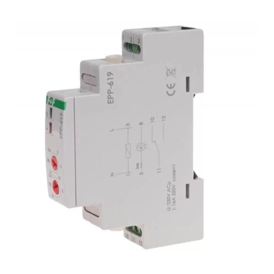
EPP-619
Electronic current
Do not dispose of this device in the trash along with other waste! According to
the Law on Waste, electro coming from households free of chage and can give
any amount to up to that end point of collec� on, as well as to store the occasion
of the purchase of new equipment (in accordance with the principle of old-for-
-new, regardless of brand). Electro thrown in the trash or abandoned in nature,
pose a threat to the environment and human health.
Purpose
The EPP-619 is a current relay is used to control the current value
in the measured circuits with the function of switching the con-
tact if the current exceeds the set threshold values.
Functioning
Power supply to the relay is signalled by the illumination of the
green LED. The potentiometer is used to set the value of the trip-
ping current. If the current value is below the set threshold the
contact remains open (pos. 11-10). If the current exceeds the set
threshold the contact will be closed (pos. 11-12) with set time
delay „t". Exceeding the set threshold is signalled by the red LED
lighting up. Decrease of the current value below the set thre-
shold will cause automatic opening of the contact (pos. 11-10).
F&F Filipowski sp. j.
Konstantynowska 79/81, 95-200 Pabianice, POLAND
phone/fax (+48 42) 215 23 83 / (+48 42) 227 09 71
www.fif.com.pl; e-mail: biuro@fif.com.pl
relay
- 1 -
Advertisement

Related Manuals for F&F EPP-619


Summary of Contents for F&F EPP-619
- Page 1 Purpose The EPP-619 is a current relay is used to control the current value in the measured circuits with the function of switching the con- tact if the current exceeds the set threshold values.
- Page 2 Diagram The current of the receiver can be greater than 16 A. The current is only limited by the cross-section of the con- ductor threaded through the through channel. Mounting 1. Switch off power supply. 2. Mount the relay on the rail in the control box. 3.
-
Page 3: Wiring Diagram
Wiring diagram Example of a system for signalling the exceeding of the set current value - 3 -... -
Page 4: Terminal Description
Terminal description 230 V relay power supply NC contact relay common COM contact NO contact - 4 -... - Page 5 Technical data power supply 195÷253 V AC contact separated 1×NO/NC maximum load current (AC-1) 16 A current measuring circuit limited cross-section of the cable switching current (adjustable) 0.6÷16 A return hysteresis activation delay (adjustable) 0.5÷10 s return delay 0.5 s power consumption 0.4 W working temperature...
-
Page 6: Warranty
Warranty The F&F products are covered by a warranty of the 24 months from the date of purchase. Effective only with proof of purchase. Contact your dealer or directly with us. CE declaration F&F Filipowski sp. j. declares that the device is in conformity with the essential requirements of The Low Voltage Directive (LVD) 2014/35/EU and the Electromagnetic Compatibility (EMC) Directive 2014/30/UE.
Need help?
Do you have a question about the EPP-619 and is the answer not in the manual?
Questions and answers