Advertisement
Quick Links
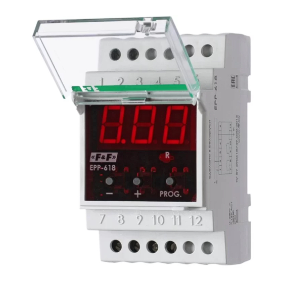
EPP-618
Electronic current
Do not dispose of this device in the trash along with other waste! According
to the Law on Waste, electro coming from households free of chage and
can give any amount to up to that end point of collec� on, as well as to sto-
re the occasion of the purchase of new equipment (in accordance with the
principle of old-for-new, regardless of brand). Electro thrown in the trash or
abandoned in nature, pose a threat to the environment and human health.
Purpose
The EPP-618 is a current relay designed to control the values of
the current flowing in the measured circuit with contact swit-
ching feature in the event of exceeding the current value above
and below the set threshold values. The digital display allows
the user to read the current value in the measured circuit on an
ongoing basis and precisely program the values of parameters
according to which it will operate.
Functioning
The relay is designed to work with a 5 A secondary current trans-
former or without a transformer, in which case its maximum
current is 50 A.
The relay operates according to one of four operating functions:
FI, F2, F3, and F4.
F&F Filipowski sp. j.
Konstantynowska 79/81, 95-200 Pabianice, POLAND
phone/fax (+48 42) 215 23 83 / (+48 42) 227 09 71
www.fif.com.pl; e-mail: biuro@fif.com.pl
relay
- 1 -
Advertisement

Related Manuals for F&F EPP-618


Summary of Contents for F&F EPP-618
- Page 1 Purpose The EPP-618 is a current relay designed to control the values of the current flowing in the measured circuit with contact swit- ching feature in the event of exceeding the current value above and below the set threshold values.
- Page 2 Function F1 If the current in the measuring circuit exceeds the "Hi" setpoint, the relay contacts 7-8 will close and the contacts 9-10 open. If the current in the measuring circuit is below the set value mi- nus the hysteresis value, the relay contacts will return to their original position.
- Page 3 Function F2 After the current falls below the "Lo" set value, the relay con- tacts 7-8 will close and the contacts 9-10 will open. If the current in the measuring circuit is above the set value plus the hysteresis value, the relay contacts will return to their origi- nal position.
- Page 4 Function F3 If the current in the measuring circuit exceeds the Hi setpoint, the relay contacts 7-8 will close and the contacts 9-10 open. The relay contacts in this function will only return to their original position if the current value is lower than Lo. In this function, the current settings are not adjusted by the hy- steresis value.
- Page 5 Function F4 In this function, the relay operates in the so called "measuring window". The relay will be switched on if the current in the measuring cir- cuit is higher than the Hi setpoint. The relay contacts will return to their original position if the current drops below the setpoint minus the hysteresis value.
-
Page 6: Display Panel
Display panel Programming the ratio value 1. Press and hold the ���� button for approximately 5 s. 2. The display will show the currently saved ratio value; the fac- tory setting is 1, or 5/5. 3. Press + or – buttons to set the desired value, for example for 100/5 transformer you need to set 20. - Page 7 Programming the operating function 1. Press and hold the + button for approximately 5 s. 2. The display will show the currently set operating function; fac- tory default is ��. 3. If the function is not changed, confirm with the ���� button. 4.
- Page 8 Connection diagram Direct mode - 8 -...
- Page 9 Measurement with a transformer - 9 -...
- Page 10 Technical data power supply 195÷253 V AC contact separated 1×NO, 1×NC maximum load current (AC-1) 2×8 A adjustment range for direct measurement 0.5÷50 A range of ratio settings 1÷999 switch-on time settings range 0.5÷60 s switch-off time settings range 0.5÷60 s constant hysteresis measurement error <3%...
-
Page 11: Warranty
Warranty The F&F products are covered by a warranty of the 24 months from the date of purchase. Effective only with proof of purchase. Contact your dealer or directly with us. CE declaration F&F Filipowski sp. j. declares that the device is in conformity with the essential requirements of The Low Voltage Directive (LVD) 2014/35/EU and the Electromagnetic Compatibility (EMC) Directive 2014/30/UE.
Need help?
Do you have a question about the EPP-618 and is the answer not in the manual?
Questions and answers