Table of Contents

Related Manuals for Measurlogic DTS 307


Summary of Contents for Measurlogic DTS 307
- Page 1 DTS 307 DIN – Rail Mounted, Ultra-Compact Revenue Grade Electrical Sub-meter 7268 S. Tucson Way, Centennial CO 80112 Page 1 ©Measurlogic Tel: 877-777-6567 Tel: 303-805-5252 MQ0052-24B e-mail: info@measurlogic.com web: www.measurlogic.com...
-
Page 2: Table Of Contents
DTS 307 ......................10 OUNTING THE IN AN LECTRICAL ANELBOARD DTS 307..........................11 TANDALONE OUNTING OF THE CONNECTING TO THE DTS 307 ............................12 ..........................12 IRING OLTAGE AND URRENT NPUTS 3.1.1 Wiring Examples ..............................12 CT ................... 14... -
Page 3: Product Overview
Our DTS 307 or DTS 307/1 energy sub-meter is one of the most versatile meters available on the market. The standard DTS 307 is a full 3-Phase measurement RGM. If only a single phase 2-Wire system needs to be measured, the single channel DTS 307/1 is also available. -
Page 4: Supplied Items
Verify that the following item(s) match with the corresponding model from the data sheet: • Installation Guide • DTS 307 power & energy meter • 10-Pin green pluggable screw terminal connector for Voltage and Aux Power/Digital Output • 6-Pin green pluggable screw terminal connector for Current inputs •... -
Page 5: Product Specification
DTS meter. des blessures corporelles et peut endommager de manière permanente le compteur DTS. The model number for the normal three-phase DTS 307 is: DTS 307 - Ax-xx-x-F For applications where only single channel measurements are needed, the model number is:... -
Page 6: Installation
• Follow all applicable local and national electric codes. • Verify input voltage and current are within thresholds for the specific DTS 307 model. (See Product Specification on page 5) • Only Current Transformers that are listed to UL 2808 for use in 250Vac or 600Vac line- to-line circuits (as appropriate for the installation) may be used with this meter. -
Page 7: Product Dimensions
• The DTS 307 may be used outdoors if housed in an outdoor rated enclosure that prevents water ingress, such as a NEMA Type 3R / IP14 or higher that is suitably rated for the application. • The enclosure must be equipped with a user supplied lock or other means to prevent unauthorized access. -
Page 8: General Mounting Requirements And Guidelines
• DTS 307 meters that have an “A” in the Service Type field of the model number (as shown in section 1.3.2) are powered through the 24Vac/dc auxiliary terminals. An external IEC 60950 compliant Class 2 isolated power supply and associated wiring methods must be used for this powering option only. - Page 9 A UL or ETL certified 600V circuit-breaker must be installed as a disconnecting device for the DTS 307 and must be positioned within easy reach of the DTS 307. The circuit-breaker employed for this disconnecting device shall meet the relevant requirements of IEC 60947-1 and IEC 60947-3, be suitable for the application, and MUST be clearly marked as being “the disconnecting device”...
-
Page 10: Mounting The Dts 307 In An Electrical Panelboard
Do not install submetering equipment in any area where breaker arc venting exhaust gasses could be re-directed as a result of submetering equipment installation. • The DTS 307 meter may NOT be installed in equipment where it exceeds 75% of the wiring space of any cross-sectional area within the equipment. •... -
Page 11: Standalone Mounting Of The Dts 307
• The DTS 307 may be used outdoors if housed in an outdoor rated enclosure that prevents water ingress, such as a NEMA Type 3R / IP14 or higher that is suitably rated for the application. -
Page 12: Connecting To The Dts 307
CONNECTING TO THE DTS 307 Wiring Voltage and Current Inputs ATTENTION ATTENTION Examine the model number of each of your Examinez le numéro de modèle de chacun de meters to ensure that they are suitable for the vos compteurs pour vous assurer qu'ils type and voltage of the service you are conviennent au type et à... - Page 13 Load→ DTS 307/1 Single Phase 2-Wire ONLY 7268 S. Tucson Way, Centennial CO 80112 Page 13 ©Measurlogic Tel: 877-777-6567 Tel: 303-805-5252 MQ0052-24B e-mail: info@measurlogic.com web: www.measurlogic.com...
-
Page 14: Configuring The Current Sensor Type And Rated Current Of The Ct
Rogowski Coil CTs (with an external integrator) – Measurlogic DTS meters can accept Rogowski Coil CTs directly connected to the DTS 307 meter, so an external integrator module is NOT required. However, if the system already has an external integrator module installed, then the output of the integrator will be 333mV for the current specified on the integrator label. - Page 15 Medium or High Voltage Applications (with external PTs): The Voltage(L-L) Primary and Secondary settings MUST be set according to the primary and secondary ratings of the external PTs. 7268 S. Tucson Way, Centennial CO 80112 Page 15 ©Measurlogic Tel: 877-777-6567 Tel: 303-805-5252 MQ0052-24B e-mail: info@measurlogic.com web: www.measurlogic.com...
-
Page 16: Connecting Multiple Loads
The measured phase current will be the total current across all the loads on that phase. • The CT primary rating for the DTS 307 must be set to the CT rating * Number of CT sets. • The example below shows how to calculate the service current for figure 3.2.1. -
Page 17: Auxiliary Power
• Connect the external IEC 60950 compliant Class 2 isolated power supply to the two 24Vac/dc terminals on the DTS 307 meter as shown on the meter label and in the diagram below. • For clarity, the meter voltage terminal and the CT sensors connections are not shown on the diagram below. -
Page 18: Dts 307 Communications Interface
à semi-conducteurs be IEC 60950 compliant. ont été certifiés conformes à la norme CEI 60950. The DTS 307 has 3 options for outputting data depending on the model ordered: • Modbus RTU over a 2-Wire RS-485 bus •... -
Page 19: Kwh Pulse Output (Model Dependent)
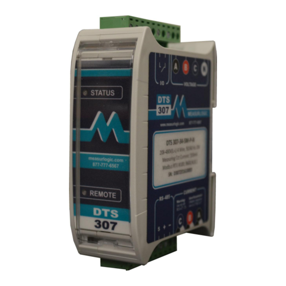
100ms between any two pulses. The maximum switching voltage is 50Vdc. LED Definitions The DTS 307 is equipped with 2 LEDs useful for diagnostics and troubleshooting – STATUS and REMOTE. Status LED • The STATUS LED consists of a repetition of two flashes and shows whether the measured power is being consumed/imported or generated/exported, as well as the magnitude of the total current. -
Page 20: Remote Led
The REMOTE LED is a communications indicator which is present on all meters fitted with an RS-485 serial port. • The LED will flicker GREEN when the DTS 307 receives data on the BUS and AMBER when the DTS 307 transmits data in response. Green – Data being received Amber –... -
Page 21: Maintenance And Service
DTS 307, please note the following: • Before attempting to clean the DTS 307 ensure that all power running to the DTS 307 is removed. • Use only a slightly damp cloth to clean the outside of the meter only.
Need help?
Do you have a question about the DTS 307 and is the answer not in the manual?
Questions and answers