Table of Contents
Advertisement
Quick Links
Advertisement
Table of Contents

Related Manuals for Measurlogic DTS 307


Summary of Contents for Measurlogic DTS 307
- Page 1 DTS 307 DIN – Rail Mounted, Ultra-Compact Revenue Grade Electrical Sub-meter 7334 S. Alton Way, Centennial CO 80112 Page 1 ©Measurlogic Tel: 877-777-6567 Tel: 303-805-5252 Fax: 425-799-4780 MQ0052-20C e-mail: info@measurlogic.com web: www.measurlogic.com...
-
Page 2: Table Of Contents
..................................6 NVIRONMENT ................................6 AFETY UIDELINES ................................7 RODUCT IMENSIONS ..........................7 OUNTING EQUIREMENTS AND UIDELINES CONNECTING TO THE DTS 307 ............................9 ............................ 9 IRING OLTAGE AND URRENT NPUTS 3.1.1 Wiring Examples ................................ 9 ............................... 11 ONNECTING ULTIPLE OADS ................................ -
Page 3: Product Overview
Our DTS 307 or DTS 307/1 energy sub-meter is one of the most versatile meters available on the market. The standard DTS 307 is a full 3-Phase measurement RGM. If only a single phase 2-Wire system needs to be measured, the single channel DTS 307/1 is also available. -
Page 4: Supplied Items
Verify that the following item(s) match with the corresponding model from the data sheet: • Installation Guide • DTS 307 power & energy meter • 10-Pin green pluggable screw terminal connector for Voltage and Aux Power/Digital Output • 6-Pin green pluggable screw terminal connector for Current inputs •... -
Page 5: Product Specification
DTS 307/1 is intended for 240V L1-L2 use Do NOT exceed this usage Use the model number of the DTS 307 to verify that it is suitable for the voltage, type and category of the installation. Failure to use the correct CT’s, and/or connecting too high a voltage can result in death or personal injury and may permanently damage the DTS meter. -
Page 6: Installation
The DTS 307 MUST be mounted in a NEC compliant enclosure suitable for the application’s environmental conditions. • The DTS 307 may be used outdoors if housed in an outdoor rated enclosure that prevents water ingress, such as a NEMA Type 3R / IP14 or higher that is suitably rated for the application. •... -
Page 7: Product Dimensions
Mount the DTS 307 as close as possible to the electrical panel being monitored. • Make sure that there is at least 4” of clearance above and below the DTS 307 for wiring and connector clearance and ¼” of clearance on both sides for cooling. - Page 8 A UL or ETL certified 600V circuit-breaker or equipment switch must be installed as a disconnecting device for the DTS 307, and must be positioned within easy reach of the DTS 307. The circuit- breaker or equipment switch employed for this disconnecting device shall meet the relevant requirements of IEC 60947-1 and IEC 60947-3, be suitable for the application, and MUST be clearly marked as being “the disconnecting device”...
-
Page 9: Connecting To The Dts 307
CONNECTING TO THE DTS 307 Wiring Voltage and Current Inputs ATTENTION Examine the model number of each of your meters to ensure that they are suitable for the type and voltage of the service you are connecting to. See section Error! Reference source not found. - Page 10 Load→ DTS 307/1 Single Phase 2-Wire ONLY 7334 S. Alton Way, Centennial CO 80112 Page 10 ©Measurlogic Tel: 877-777-6567 Tel: 303-805-5252 Fax: 425-799-4780 MQ0052-20C e-mail: info@measurlogic.com web: www.measurlogic.com...
-
Page 11: Connecting Multiple Loads
The measured phase current will be the total current across all the loads on that phase. • The CT primary rating for the DTS 307 must be set to the CT rating * Number of CT sets. • The example below shows how to calculate the service current for figure 3.2.1. -
Page 12: Auxiliary Power
Auxiliary Power ATTENTION DTS 307 meters that have an “A” in the Service Type field of the model number (as shown in section 1.3.2) require an external 24Vac/dc auxiliary power supply to operate. A separate IEC 60950 compliant isolated 24Vac/dc power supply MUST be used to power these meters. -
Page 13: Dts 307 Communications Interface
RS-485 communications bus, and/or the digital solid state relay output have been certified to be IEC 60950 compliant. The DTS 307 has 3 options for outputting data depending on the model ordered: • Modbus RTU over a 2-Wire RS-485 bus •... -
Page 14: Kwh Pulse Output (Model Dependent)
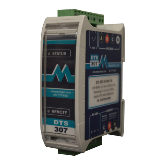
100ms between any two pulses. The maximum switching voltage is 50Vdc. LED Definitions The DTS 307 is equipped with 2 LEDs useful for diagnostics and troubleshooting – STATUS and REMOTE. Status LED • The STATUS LED consists of a repetition of two flashes and shows whether the measured power is being consumed/imported or generated/exported, as well as the magnitude of the total current. -
Page 15: Remote Led
DTS 307, please note the following: • Before attempting to clean the DTS 307 ensure that all power running to the DTS 307 is removed. • Use only a slightly damp cloth to clean the outside of the meter only.
Need help?
Do you have a question about the DTS 307 and is the answer not in the manual?
Questions and answers