Table of Contents
Advertisement
Quick Links
Advertisement
Table of Contents

Related Manuals for Measurlogic DTS SMX


Summary of Contents for Measurlogic DTS SMX
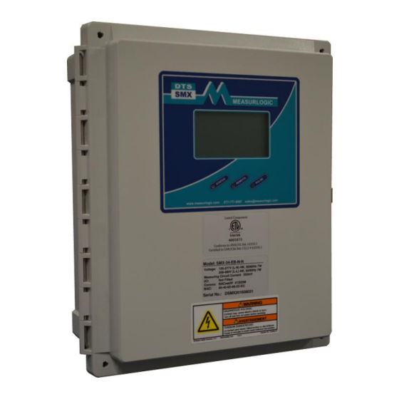
- Page 1 DTS SMX Surface mounting, outdoor rated Revenue grade electrical sub-meter 7334 S. Alton Way, Centennial CO 80112 Page 1 ©Measurlogic Tel: 877-777-6567 Tel: 303-805-5252 Fax: 425-799-4780 MQ0051-20F e-mail: info@measurlogic.com web: www.measurlogic.com...
-
Page 2: Table Of Contents
INSTALLATION ................................... 6 ................................6 AFETY UIDELINES ................................7 RODUCT IMENSIONS ..........................7 OUNTING EQUIREMENTS AND UIDELINES CONNECTING TO THE DTS SMX ............................9 ................................9 OLTAGE ONNECTIONS 2 PT ) ......................10 OLTAGE ONNECTIONS EDIUM OLTAGE WITH CT ............................11 OGOWSKI 3.3.1... -
Page 3: Product Overview
The one revenue grade meter for all applications. Your new DTS SMX energy sub-meter is one of the most versatile meters available on the market. The DTS SMX can operate in any environment, requires no external power source to operate, and works with all UL or ETL listed 333mV and 1A/5A current transformers (model dependent). -
Page 4: Document Conventions
Only use the CT’s that came with the unit Note: Make sure that the DIP Switch settings on the DTS SMX are set to the correct CT Primary. See section 5.3.1 on page 20. If all Dip Switch settings on the DTS SMX are “off”... -
Page 5: Dts Smx Layout
DTS SMX Layout The following figure shows the layout of the DTS SMX as well as the section number and pages of the installation guide that describe how to interact with each of the features of the DTS SMX. Note that not all features listed here are included with every DTS SMX. Please refer to the model number to determine which features are included. -
Page 6: Installation
TRANSFORMER OTHER THAN THE ONE SPECIFIED BY THE DTS MODEL CAN RESULT IN PERMANENT DAMAGE TO THE DTS SMX. • Ensure that the in-line fuses located on the main board of the DTS SMX are fitted and securely fastened. •... -
Page 7: Product Dimensions
Position the DTS SMX such that the labeling and screen can be read from the upright position. • Do not use the DTS SMX enclosure as a guide to drill mounting holes. This can damage the DTS SMX enclosure. 7334 S. Alton Way, Centennial CO 80112 Page 7 ©Measurlogic... - Page 8 It is recommended that two separate conduits be run for voltage and current connections. • If installing the DTS SMX outdoors, run the electrical conduits from the bottom of the DTS SMX to the electrical panel being monitored. If necessary install drip hook/loops to allow water to flow away from the DTS SMX or electrical panel.
-
Page 9: Connecting To The Dts Smx
CONNECTING TO THE DTS SMX Voltage Connections The DTS SMX comes with easy to use voltage connection points and in-line fuse connections. ATTENTION Voltage connections should come from the same lines that the CT’s will be connected to. In-line fuse clips. See section 4.1 for fuse... -
Page 10: S )
PT itself. Use wiring according to national code and as recommended by the PT manufacturer. Load→ Source 7334 S. Alton Way, Centennial CO 80112 Page 10 ©Measurlogic Tel: 877-777-6567 Tel: 303-805-5252 Fax: 425-799-4780 MQ0051-20F e-mail: info@measurlogic.com web: www.measurlogic.com... -
Page 11: 333Mv And Rogowski Coil Ct
333mV and Rogowski Coil CT ATTENTION Make sure that your model of DTS SMX is approved for the following wiring guidelines. Note: CTs should be connected to the same panel as the voltage connections. 3.3.1 Single Phase 2/3 Wire Example... -
Page 12: Connecting The Cts From Multiple Loads To The Screw Terminals
The measured phase current will be the total current across all the loads on that phase. • The CT primary rating for the DTS SMX must be set to the CT rating * Number of CT sets. • The example below shows how to calculate the service current for figure 3.1.1. -
Page 13: Connecting The Cts From Multiple Loads To The 333Mv Ct Daughter Board
Connecting the CTs from Multiple Loads to the 333mV CT Daughter Board The optional 333mV CT daughter board for the DTS SMX provides an easier way to connect up to three (3) CTs per phase to the DTS SMX meter. The technical details in Section 3.3.3 also apply to this section. -
Page 14: Amp Secondary Ct Daughter Board
Feed WHITE Wire through CTs on Main Board Make sure CT arrows point TOWARDS the LOAD Breaker → Load→ Source 7334 S. Alton Way, Centennial CO 80112 Page 14 ©Measurlogic Tel: 877-777-6567 Tel: 303-805-5252 Fax: 425-799-4780 MQ0051-20F e-mail: info@measurlogic.com web: www.measurlogic.com... -
Page 15: Dts Smx Digital I/O Circuit (Optional)
Failure to do so may result in electric shock or arc risk. The only user serviceable parts inside the DTS SMX are the voltage fuses and coin cell battery. The detailed parts specifications and replacement procedures can be found in sections 4.1 and 4.2. -
Page 16: Voltage Fuses
Voltage Fuses The DTS SMX is fitted with three in-line fuses. See section 4.1.2 for the replacement procedure. 4.1.1 Voltage Fuse Specifications The voltage inputs are fitted with fusing appropriate for the model of meter ordered (represented by F1-F3 in the diagrams below) and are rated at 2A 600Vac for 480V systems or 2A 250V for 208V systems. -
Page 17: Battery
Figure 4.2b – Battery Orientation Figure 4.2a – Location of battery • The coin cell battery is located in the upper left on the main board of the DTS SMX as shown in figure 4.2a. • When replacing the battery make sure that the “+” side of the battery is facing the same direction as the “+”... -
Page 18: Disposal
Lithium coin batteries lodged in the esophagus should be removed immediately. Leakage, chemical burns and perforation can occur within hours of ingestion. 7334 S. Alton Way, Centennial CO 80112 Page 18 ©Measurlogic Tel: 877-777-6567 Tel: 303-805-5252 Fax: 425-799-4780 MQ0051-20F e-mail: info@measurlogic.com web: www.measurlogic.com... -
Page 19: Dts Smx Communications Interface
BACnet MAC Address & Device ID: 100, Baud Rate 38400, Parity: None, Data Bits: 8, Stop Bits: 1. This is notated as 38400,N,8,1. This is denoted as SW1-1 ON and SW1-2 through 8 switches OFF and is how each DTS SMX is shipped (See Section 5.3.1 below). -
Page 20: Ethernet Communications
Configuring the DIP Switches – Communications Settings, CT Ratings and Other Options The DTS SMX has two 8-way DIP switches that provide the user a simple and flexible interface for configuration. The right hand side block of DIP switches (SW1) are used to set up the device’s address and baud rate for RS- 485 interfaces, while the left hand side block of DIP switches (SW2) control display, digital output, and CT ratio options. -
Page 21: Ct Ratings, Digital Output Mapping And Backlight
CT Primary switches MUST also be left in the OFF position. Please see the next pages for more details. 7334 S. Alton Way, Centennial CO 80112 Page 21 ©Measurlogic Tel: 877-777-6567 Tel: 303-805-5252 Fax: 425-799-4780 MQ0051-20F e-mail: info@measurlogic.com web: www.measurlogic.com... - Page 22 Switch 2 – CT Primary Current Rating (333mV and 5A CTs ONLY) The DTS SMX is available with different CT Primary Current Rating Tables as described below. • On the table printed on the silkscreen on the display PCB itself (MLB0010-B).
- Page 23 All the CT Primary switches MUST be left in the OFF position. DO NOT change the “CT Primary” settings on Switch 2. 7334 S. Alton Way, Centennial CO 80112 Page 23 ©Measurlogic Tel: 877-777-6567 Tel: 303-805-5252 Fax: 425-799-4780 MQ0051-20F e-mail: info@measurlogic.com web: www.measurlogic.com...
- Page 24 All the CT Primary switches MUST be left in the OFF position. DO NOT change the “CT Primary” settings on Switch 2. 7334 S. Alton Way, Centennial CO 80112 Page 24 ©Measurlogic Tel: 877-777-6567 Tel: 303-805-5252 Fax: 425-799-4780 MQ0051-20F e-mail: info@measurlogic.com web: www.measurlogic.com...
-
Page 25: Led Definitions
BUS and AMBER when the DTS SMX transmits data in response. Pulse LED The PULSE LED flashes AMBER when the DTS SMX pulses the digital output relay after the specified amount of energy has elapsed. INSTALLATION OF DTS CONFIG AND MONITORING SOFTWARE •... -
Page 26: Dts Smx To Server
The following is a typical diagram showing connections of one or more DTS SMX meters to a Master Application. DTS SMX to Server Unit 1 Unit 2 Unit X Red Wire = + Green Wire = Gnd or Shield Black Wire = –...
Need help?
Do you have a question about the DTS SMX and is the answer not in the manual?
Questions and answers
How to configure DTS SMX output to read per unit per day
The DTS SMX output can be configured using DTS Config software. To configure output for per unit per day readings:
1. Use digital outputs (potential-free solid state N.O. relays) for energy pulses.
2. Channel 3 (marked “PULSE OUT”) provides kWh pulse output.
3. Set pulse rate using Switches 2.1 and 2.2 as described in Section 5.3.2.
4. Use DTS Config to define pulse output based on energy usage.
5. Collect and sum pulses over a 24-hour period to calculate per unit per day.
Direct setting for "per unit per day" output is not mentioned, so data must be processed externally based on pulse counts.
This answer is automatically generated