Table of Contents
Advertisement
Advertisement
Table of Contents

Subscribe to Our Youtube Channel
Related Manuals for Vaisala DRYCAP DM70


Summary of Contents for Vaisala DRYCAP DM70
- Page 1 M010091EN-G User Guide â Vaisala DRYCAP Handheld Dew Point Meter DM70...
- Page 2 English versions are This product contains software developed applicable, not the translations. by Vaisala or third parties. Use of the The contents of this document are subject software is governed by license terms and to change without prior notice.
-
Page 3: Table Of Contents
Table of contents Table of contents About this document..................7 Version information..................7 Related manuals....................7 Documentation conventions................8 Trademarks......................8 Product overview.................... 9 Introduction to DM70..................9 Basic features and options................10 Parts description....................11 MI70 indicator....................12 MI70 indicator parts..................12 Installing and recharging MI70 batteries............12 3.2.1 MI70 battery status information.............13 MI70 first start-up settings................14... - Page 4 DM70 User Guide M010091EN-G Settings menu....................36 5.8.1 User interface settings................36 Date and time....................38 5.10 Measurement settings................... 39 5.11 Setting calibration reminder................. 39 5.12 Device information..................40 5.13 Factory settings....................41 Field calibration check of fixed transmitters........42 Field calibration check of DMT340/DMT242/DMT143......42 Sampling from processes................44 Sampling cells....................44 7.1.1...
- Page 5 Table of contents 10.2 MI70 specifications..................78 10.3 Dimensions..................... 80 10.4 Spare parts and accessories................. 80 Maintenance and calibration services............83 Technical support.................... 83 Warranty......................83 Recycling......................83...
- Page 6 DM70 User Guide M010091EN-G List of figures Figure DM70 parts......................11 Figure 2 MI70 indicator parts..................12 Figure 3 Display example with carbon dioxide and temperature and humidity probes connected simultaneously........18 Figure 4 DM70 basic display..................19 Figure 5 DM70 menus......................21 Figure 6 Quantities and units menu................23 Figure 7...
- Page 7 List of tables List of tables Table 1 Document versions (English)................7 Table 2 Related manuals....................7 Table 3 Display parameters....................9 Table 4 MI70 battery status indicator................13 Table 5 MI70 status icons....................22 Table 6 DM70 handheld meter general specifications........... 73 Table 7 DMP74A, DMP74B, and DMP74C measurement performance....
- Page 8 DM70 User Guide M010091EN-G...
-
Page 9: About This Document
Chapter 1 – About this document 1. About this document 1.1 Version information This document provides detailed instructions for using and maintaining Vaisala DRYCAPâ Handheld Dew Point Meter DM70. Table 1 Document versions (English) Document code Date Description M010091EN-G October This document. 2020 •... -
Page 10: Documentation Conventions
Lists tools needed to perform the task. Indicates that you need to take some notes during the task. 1.4 Trademarks Vaisalaâ and DRYCAPâ are registered trademarks of Vaisala Oyj. Windowsâ is either a registered trademark or trademark of Microsoft Corporation in the United States and other countries. -
Page 11: Product Overview
2. Product overview 2.1 Introduction to DM70 Vaisala DRYCAPâ Handheld Dew Point Meter DM70 measures dew point temperature accurately in a measurement range from −60 °C up to +60 °C (−76 ... +140 °F) depending on the probe model. DM70 incorporates the advanced DRYCAPâ technology, which enables reliable and high-performance dew point measurement. -
Page 12: Basic Features And Options
• A possibility for an analog output (voltage signal 0 ... 1 V) • Multiprobe operation; any combination of 2 Vaisala DM70, GM70, HM70, and MM70 series probes can be used, for example, for simultaneous dew point and relative humidity measurements •... -
Page 13: Parts Description
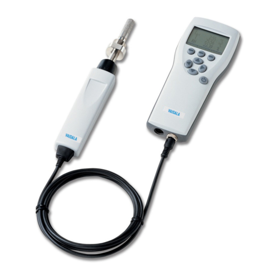
Chapter 2 – Product overview 2.3 Parts description Figure 1 DM70 parts Charger socket MI70 indicator Connector ports for probes and cables Calibration button Sampling cell DSC74 (optional) DMP74 probe... -
Page 14: Mi70 Indicator
DM70 User Guide M010091EN-G 3. MI70 indicator 3.1 MI70 indicator parts Figure 2 MI70 indicator parts Charger socket Function key shortcut buttons . The functions change according to what you are doing with the indicator. Arrow buttons: Move up in a menu Move down in a menu Enter a sub-menu Return to previous menu level Power On/Off button... -
Page 15: Mi70 Battery Status Information
MI70 screen. You can order replacement batteries from Vaisala (item code 26755). To keep the rechargeable MI70 battery in good working condition, recharge MI70... -
Page 16: Mi70 First Start-Up Settings
DM70 User Guide M010091EN-G More information ‣ Spare parts and accessories (page 80) 3.3 MI70 first start-up settings When you switch on MI70 for the first time, configure the basic settings (time, date, language) as instructed below. 1. Connect the probe to either one of the base connectors in the indicator. To ensure a durable connection, screw the metal ring clockwise until it tightens up. - Page 17 Chapter 3 – MI70 indicator In case you are installing a battery pack and you have a device with alkaline batteries, remove the metal contact from the probe port end of the battery compartment before installing the battery pack. 1. Open the back plate of the indicator by opening the screw of the back plate. 2.
-
Page 18: Dew Point Measurement
DM70 User Guide M010091EN-G 4. Dew point measurement 4.1 Measurement in dry environments The following recommendations should be taken into account when measuring in very dry environments: • A clean environment is always best for humidity measurements. • The number of connections should be minimized to avoid leaks. •... -
Page 19: Measuring Multiple Parameters Simultaneously
‣ Turning automatic sensor purge on and off (page 31) 4.3 Measuring multiple parameters simultaneously MI70 is a generic indicator that can be used with Vaisala interchangeable dew point (DM70 series), humidity (HM70 series), carbon dioxide (GM70 series), and moisture in oil (MM70 series) probes. -
Page 20: Figure 3 Display Example With Carbon Dioxide And Temperature And Humidity Probes Connected Simultaneously
DM70 User Guide M010091EN-G 5. The reading of the probe in port I is now displayed on the upper row(s) and the reading of the probe in port II on the lower row(s) of the MI70 display. Figure 3 Display example with carbon dioxide and temperature and humidity probes connected simultaneously... -
Page 21: User Interface
Chapter 5 – User interface 5. User interface 5.1 Basic display Figure 4 DM70 basic display Battery indicator. Shows the current status (charge) of the battery. Pressure setting. Measured parameter (up to 3 items on display simultaneously). You can change the shown items in Main menu > Display > Quantities and units. Function key Graphic shows the readings as a curve. - Page 22 DM70 User Guide M010091EN-G 2. Press any arrow button, then select Open (must be pressed within 5 seconds or the indicator returns to the basic display). 3. Move in the menus using the buttons. 4. Select an item with the button.
-
Page 23: Figure 5 Dm70 Menus
Chapter 5 – User interface 6. To return to normal operation, press Exit. Figure 5 DM70 menus... -
Page 24: Mi70 Status Icons
DM70 User Guide M010091EN-G 5.3 MI70 status icons Icons that inform you about the status of MI70 (for example, battery status and alarm notification) are shown on the upper left corner of the display. Multiple icons can be shown simultaneously. Table 5 MI70 status icons Icon Description Battery status icon. -
Page 25: Display Menu
Chapter 5 – User interface More information ‣ MI70 battery status information (page 13) ‣ Recording data (page 33) ‣ Setting calibration reminder (page 39) ‣ Selecting and scaling analog output (page 26) ‣ Transferring recorded data to PC with MI70 Link (page 35) ‣... -
Page 26: Rounding
DM70 User Guide M010091EN-G 8. If you want to check the environment settings, press Yes. Otherwise press Units °C atm and °F atm indicate that the dew point or frost point is converted from process pressure to atmospheric pressure. 5.4.2 Rounding 1. -
Page 27: Graphical Display
Chapter 5 – User interface 4. Select the saved display based on date and time by pressing the right arrow button. 5.4.4 Graphical display The graphical display shows you the measurements as a curve (the curve of the uppermost parameter shown in the basic display). From the curve you can examine the data trend and history of the last minutes. -
Page 28: Selecting And Scaling Analog Output
Yes. To discard the alarm, press The alarm does not work when the device is powered off. 5.5.2 Selecting and scaling analog output To get analog measurement data, an analog signal cable is needed (Vaisala item code 27168ZZ). -
Page 29: Autocalibration
Chapter 5 – User interface Figure 7 Analog output menu 1. Connect the signal cable connector of the analog output to the base connector of the MI70 indicator. Connect the screw terminal block as follows: Wire Connect to Brown wire Common wire (−) Yellow-green wire Signal (+) 2. - Page 30 DM70 User Guide M010091EN-G • Humidity environment must be stable. The maximum change in the dew point can be 1 °C within 30 seconds. Autocalibration cannot operate if the above criteria are not met. If the adjustment in the autocalibration reaches a preset, maximum value or if the autocalibration correction fails, for example, because of unstable conditions, a new autocalibration may take place later (if the automatic autocalibration is turned on).
- Page 31 Chapter 5 – User interface 4. If you want to start autocalibration, press Yes. If the autocalibration conditions are not fulfilled, a note appears on the display informing that the calibration cannot be made or that a new attempt will be made later.
- Page 32 DM70 User Guide M010091EN-G 5. When the autocalibration is completed, the display returns to the basic display automatically. If it is too humid, autocalibration will not start. a. Display during the adjustment period (< 15 seconds). b. Adjustment period is completed and stabilization period will start. c.
-
Page 33: Sensor Purge
Chapter 5 – User interface e. Autocalibration is completed. 5.5.4 Sensor purge Sensor purge feature is only available in the DMP74B/DMP74C probe. The purge should be carried out to achieve the shortest response times and the best long-term stability. Sensor purge is an automatic procedure, in which the sensor is dried. Thus, the sensor will response very fast when installing the probe from an ambient to a dry gas. - Page 34 DM70 User Guide M010091EN-G 1. Open the menu by pressing Open. 2. Select Settings and press 3. Select Measurement settings and press 4. Select Autom. Purge and press 5. To turn the automatic sensor purge off, press Off. To reactivate the automatic sensor purge, press Off.
-
Page 35: Recording/Viewing Menu
Chapter 5 – User interface 4. When the sensor purge is completed, the display returns to the basic display automatically. The stabilization of the temperature reading can take a few minutes. If the dew point is low, automatic autocalibration will take place immediately after the sensor purge. -
Page 36: Viewing Recorded Data
DM70 User Guide M010091EN-G Figure 9 Recording/Viewing menu 5.6.2 Viewing recorded data 1. Open the menu by pressing Open. 2. Select Recording/Viewing and press 3. Select View recorded data and press 4. Select the file you want to view and press . The files are identified according to the starting date and time of recording. -
Page 37: Transferring Recorded Data To Pc With Mi70 Link
Exit. 5.6.5 Transferring recorded data to PC with MI70 Link PC data transfer requires the MI70 Link Windowsâ software and a Vaisala USB cable (item code 219687). The serial connection cable can also be used for MI70 Link data transfer. The MI70 Link software is available from the Vaisala website: www.vaisala.com/mi70link. -
Page 38: Settings Menu
DM70 User Guide M010091EN-G 2. Select Environment with and press 3. To change the pressure unit, press Unit. The default unit is barg. 4. To change the ambient pressure value, press Set. 5. Set the value using the arrow buttons. To change the sign of the pressure value, press +/-. - Page 39 Chapter 5 – User interface 6. To return to the basic display, press Exit. 5.8.1.2 Correcting language selection 1. Return to the basic display by pressing the rightmost button until the basic display appears. 2. Go to the Language selection menu by pressing first and then the button in the middle.
-
Page 40: Date And Time
DM70 User Guide M010091EN-G 7. To return to the basic display, press Exit. Figure 11 Hold/Save replaced by AutoCal 5.8.1.5 Configuring button tones and backlight To turn on or off the backlight or the sound effects for the buttons: 1. Open the menu by pressing Open. -
Page 41: Measurement Settings
Chapter 5 – User interface 5. For the desired time, select Time and press Set. Use the arrow buttons to change the time. To confirm the selection, press OK. To change the time format, select 12-hour clock and press On/Off. 6. -
Page 42: Device Information
DM70 User Guide M010091EN-G Figure 13 Calibration reminder menu Make sure the MI70 date and time settings are correct when using the calibration reminder. 1. Open the menu by pressing Open. 2. Select Settings and press 3. Select Calibr. reminder and press Set. -
Page 43: Factory Settings
Chapter 5 – User interface 5. To return to the basic display, press Exit. Figure 15 Indicator and probe information Software version of the MI70 indicator Serial number of the MI70 indicator Probe type Software version of the probe Serial number of the probe 5.13 Factory settings Factory settings can be restored to clear all the changed settings and data memory of the indicator. -
Page 44: Field Calibration Check Of Fixed Transmitters
To compare measurement readings or to read the output of a fixed transmitter directly on the DM70 display, connect DM70 to a fixed Vaisala transmitter using the connection cable accessories. Vaisala DRYCAPâ Dew Point and Temperature Transmitter Series DMT340 can be adjusted in laboratory conditions using DM70 as a reference. - Page 45 3 ˚C, there is no immediate need for adjustment. However, in applications where optimum accuracy is essential, it is recommended to send the DMT340/DMT242/DMT143 transmitter to Vaisala if the difference is considered significant.
-
Page 46: Sampling From Processes
DM70 User Guide M010091EN-G 7. Sampling from processes 7.1 Sampling cells When the dew point of a process needs to be measured using DM70, the process can be sampled using one of the following devices: • DSC74 • DSC74B • DSC74C • DSS70A •... -
Page 47: Dsc74B
Chapter 7 – Sampling from processes Figure 16 DSC74 sampling cell with adapters Thread adapter type 3/8" - 1/2"G Thread adapter type 3/8" - 1/4"G NIP08, type D Leakage screw Sampling cell DSC74 7.1.2 DSC74B • Sampling cell, thread 3/8"G • Connection part with a needle valve and an integrated leakage screw •... -
Page 48: Dsc74C
DM70 User Guide M010091EN-G Figure 17 DSC74B Gas goes in Gas comes out 7.1.3 DSC74C • Sampling cell, thread 3/8"G • Connection part with a needle valve and an integrated leakage screw • Reducing nipple (thread adapter), 3/8"G - 1/2"G • Reducing adapter (thread adapter), 3/8"G - 1/4"G •... -
Page 49: Dmt242Sc And Dmt242Sc2
Chapter 7 – Sampling from processes Figure 19 Alternative assembly of DSC74C for tight spaces Gas comes out Coil Thread, max. size 7 mm Gas goes in Valve 7.1.4 DMT242SC and DMT242SC2 • DMT242SC is a sampling cell with threads 3/8"G and 1/4"G. •... -
Page 50: Connecting To Pressurized Processes Using Dsc74 Sampling Cell
7.2 Connecting to pressurized processes using DSC74 sampling cell DSC74 is a Vaisala sampling cell for connecting DM70 to pressurized processes (optional accessory). With DSC74B and DSC74C, measuring can be done in overpressure or atmospheric pressure. This depends on whether the sample gas is let into the sample cell before the needle valve or after that. - Page 51 Chapter 7 – Sampling from processes To connect to a pressurized process using DSC74: 1. Check that the HM70 pressure setting is correct (same as the process pressure). For instructions, see Configuring pressure settings (page 35). 2. Select the quick connector or thread adapter that matches your process fitting. 3.
-
Page 52: Figure 21 Turning Sampling Cell Valve Screw With Flathead Screwdriver
DM70 User Guide M010091EN-G 8. Make sure that the valve of the sampling cell is open. First close the valve, then turn it halfway open again. You can also first open the valve more to ventilate the parts, then readjust it to allow only a small leakage. Figure 21 Turning sampling cell valve screw with flathead screwdriver To verify that the leak screw is open, close the screw and then listen for a barely audible hiss when reopening the screw (1/2 turn). -
Page 53: Dss70A Sampling System
• If the sample is taken from a pressurized process (1.2 ... 20 bar), the sample pump must be turned off and the tube from the flowmeter to the pump must be detached. The DSS70A sampling system can be ordered from Vaisala separately or in connection with the DM70 meter. -
Page 54: Dss70A Sampling Procedure
DM70 User Guide M010091EN-G Figure 22 DSSA70A portable sampling system Fuses Inline filter (7 µm) MI70 recharger adapter Pump on/off MI70 indicator Sample valve Sampling tube Sample gas inlet and outlet Flowmeter Detach this tube when sampling from pressurized processes 7.3.1 DSS70A sampling procedure To take a sample from a process using DSS70A: 1. -
Page 55: Recharging Dss70A Battery
Chapter 7 – Sampling from processes 4. Remove the inlet/outlet plugs. 5. Insert the 1/4" tubing into the IN fitting. Tighten the nut 11/4 turns with an open-ended, 14- mm spanner to make a gas-tight fitting. In future, only slight tightening with an open- ended spanner is needed to make a gas-tight fitting. -
Page 56: Changing Dss70A Battery
DM70 User Guide M010091EN-G 7.3.3 Changing DSS70A battery Replacement batteries can be ordered from Vaisala (see Spare parts and accessories (page 80)). To change the battery: 1. The battery is fitted underneath the sampling system. To change the battery, lift the sampling system from the briefcase. -
Page 57: Figure 24 Sampling System Upside Down
Chapter 7 – Sampling from processes 2. Turn the sampling system upside down (see Figure 24 (page 55)). Figure 24 Sampling system upside down Battery Battery wires Nut of the sample oil 3. Detach the battery wires. Remove the old battery by pulling it up. The battery is attached to its place with double-sided tape. -
Page 58: Changing Dss70A Filter
The filter may need to be changed after several hundreds of hours or after years. A dry filter may cause increased response times. A new filter can be ordered from Vaisala (see Spare parts and accessories (page 80)). -
Page 59: Changing Dss70A Fuses
Chapter 7 – Sampling from processes 7.3.5 Changing DSS70A fuses To change the DSS70A fuses: 1. Press down the fuse button and simultaneously turn it. 2. Replace the old fuse with a new one of same type and rating (glass tube fuse 5 × 20 mm T 2 A / 250 VAC). -
Page 60: Measuring Moisture In Sf Gas-Insulated Equipment
DM70 User Guide M010091EN-G 8. Measuring moisture in SF gas- insulated equipment 8.1 Overview Sulfur hexafluoride (SF ) is an inert, insulating gas of high dielectric strength and thermal stability. SF is used to insulate high voltage lines, circuit breakers, and other equipment used in transmission and distribution of electricity. -
Page 61: Operating Environment
Chapter 8 – Measuring moisture in SF6 gas-insulated equipment 8.2 Operating environment A typical dew point of pure SF is usually around −60 °C. The recommendations for the moisture limit of the equipment insulated with gas (GIE) vary between 70 ... 810 ppm , which corresponds to −45 ... - Page 62 DM70 User Guide M010091EN-G Parts per million by volume (ppm ) and parts per million by weight (ppm ) are frequently used to indicate humidity. The latter depends on the molecular weight of the gas. For SF , the molecular weight is 146.06, and the conversion between ppm and ppm is the following: = ppm...
-
Page 63: Calibration And Adjustment
After the adjustment, the original calibration certificate shipped with the product is no longer valid. Read the instructions through carefully before making any adjustments. Dew point calibration should be carried out in Vaisala or in other laboratory conditions. 9.3 Adjusting DM70 The reference condition of the dew point must be traceable to the appropriate standards. -
Page 64: Adjusting Dmt340 Series Transmitters Using Dm70 As Reference Or Terminal
9.4 Adjusting DMT340 series transmitters using DM70 as reference or terminal Vaisala DRYCAPâ Dew Point and Temperature Transmitter Series DMT340 can be adjusted using a correctly adjusted DM70 as a reference dew point meter. Note that dew point adjustment should be carried out in laboratory conditions and not in the field. The adjustment procedure for DMT340 using DM70 as a reference is very similar to the adjustment of the DMP74B/DMP74C probes. - Page 65 Chapter 9 – Calibration and adjustment 2. When using the DMP74B probe, do the manual sensor purge. For instructions, see Performing manual sensor purge (page 32) 3. Remove the screw from the probe handle to expose the calibration button (see Figure 1 (page 11)) and press the button, for example, with a small screwdriver.
-
Page 66: Making A 2-Point %Rh Adjustment Of Dmt340 Series Transmitters Using Dm70
DM70 User Guide M010091EN-G 9.5.2 Making a 2-point %RH adjustment of DMT340 series transmitters using DM70 DM70 can be used for making a 2-point relative humidity adjustment of DMT340 series transmitters. For DMT340 M-sensor, humidity references of 0 % (for example nitrogen) and 10 ... 20 % are required. -
Page 67: Td/F Adjustment Of Dm70
Chapter 9 – Calibration and adjustment 14. To return to the basic display, press Exit. If there is a temperature difference between the generated reference and the probe temperature, relative humidity must be calculated to correspond to the temperature of the probe. -
Page 68: Td/F Adjustment Of Dmt340 Series Transmitters Using Dm70
DM70 User Guide M010091EN-G 14. To seal the calibration, attach a sticker on the calibration button. Several autocalibrations may be necessary after this adjustment has been performed until the transmitter reaches full accuracy. 9.5.4 Td/f adjustment of DMT340 series transmitters using DM70 For DMT340 series transmitters with the M-sensor, the sensor purge must be performed manually 1 hour before adjusting the dew point. - Page 69 Chapter 9 – Calibration and adjustment 9.5.4.1 To same as T d/f I/II This procedure is one of the alternative options for completing the adjustment described in Td/f adjustment of DMT340 series transmitters using DM70 (page 66). This adjustment method automatically uses the reading of the reference probe as the reference value for making the adjustment.
-
Page 70: Adjusting Temperature
DM70 User Guide M010091EN-G 1. A note is displayed on the screen reminding you to follow the adjustment procedure described in the DMT340 User's Guide. Press OK to proceed with the adjustment. 2. Follow the stabilization from the graphic display by pressing Graph. - Page 71 Chapter 9 – Calibration and adjustment 4. To select the adjustment method, first press Adjust and then choose the adjustment method, either 1-point adjustment or 2-point adjustment. 5. Depending on your selection, continue with the instructions in 1-point adjustment (page 69) 2-point adjustment (page 69).
-
Page 72: Temperature Adjustment Of Dmt340 Series Using Dm70
DM70 User Guide M010091EN-G 6. Confirm the adjustment by pressing Yes. If you press No, you return to the adjustment display and no changes are made. If the difference between the 2 references is less than 30 %, the adjustment cannot be done. - Page 73 Chapter 9 – Calibration and adjustment 1. After selecting To same as T , confirm the adjustment by pressing Yes. If you press I/II No, a note is displayed on the screen reminding you to follow the adjustment procedure described in the DMT340 User's Guide. Press OK and the adjustment mode display returns and no changes are made.
- Page 74 DM70 User Guide M010091EN-G 6. Confirm the adjustment by pressing Yes. If you press No, you return to the adjustment mode display and no changes are made. If the difference between the two references is less than 30 °C, the adjustment cannot be done.
-
Page 75: Technical Data
Chapter 10 – Technical data 10. Technical data 10.1 DM70 and DMP74 specifications Table 6 DM70 handheld meter general specifications Property Description/value Storage temperature −40 … +70 ˚C (−40 … +158 ˚F) Storage humidity range 0 … 100 % non-condensing Housing material ABS/PC blend Total weight 750 g (26 oz) Electromagnetic compatibility... - Page 76 DM70 User Guide M010091EN-G Property Description/value −60 … 0 ˚C T (−76 … +32 ˚F T 10 s (20 s) Temperature Measurement range −10 … 60 ˚C (14 … 140 ˚F) Accuracy at +20 ˚C (+68 ˚F) ±0.2 ˚C (±0.36 ˚F) Typical temperature dependence of electronics ±0.005 ˚C/˚C (±0.005 °F/°F) Temperature sensor...
-
Page 77: Figure 28 Dmp74A Dew Point Accuracy Vs. Measurement Conditions
SF gas. Table 8 DMP74A, DMP74B, and DMP74C general specifications Property Description/value Sensor DMP74A: Vaisala DRYCAPâ 180S DMP74B/DMP74C: Vaisala DRYCAPâ 180M Probe material (wetted parts) Stainless steel (AISI 316L) Sensor protection Sintered filter, (AISI 316L), item No. HM47280SP... -
Page 78: Table 9 Dmp74A, Dmp74B, And Dmp74C Mechanical Specifications
DM70 User Guide M010091EN-G Property Description/value Mechanical connection G1/2" ISO2281 thread with bonded seal ring (U- seal) Housing classification IP65 (NEMA4) Storage temperature −40 … +70 ˚C (−40 … +158 ˚F) Storage humidity 0 … 100 %RH non-condensing Weight 350 g (12 oz) Table 9 DMP74A, DMP74B, and DMP74C mechanical specifications Property Description/value... - Page 79 Chapter 10 – Technical data Property Description/value Weight 285 g (10 oz) DSC74 sampling cell for pressurized gases Quick connector Type D/NIP08 Leak screw Screwdriver operated Inlet/outlet thread ISO G 3/8"/G 1/4" Thread adapters included A) ISO G 3/8" to G 1/4" (female) B) ISO G 3/8"...
-
Page 80: Mi70 Specifications
DM70 User Guide M010091EN-G Property Description/value Operating pressure With pump: 0.6 … 1.2 bar (8.7 … 17.4 psi Pump disconnected: 0 … 20 bar (0 … 290 psi Battery operation time for pump 8 h continuous Filter 7 mm (0.28 in) inline filter, 1/4" SWAGELOK SS-4F-7 Wetted parts Stainless steel... -
Page 81: Table 12 Mi70 Battery Operation Time
Chapter 10 – Technical data Property Description/Value Weight 400 g (14 oz) Compatibility EMC compliance EN 61326-1, portable equipment Other Menu languages English, Chinese, Spanish, Russian, French, Japanese, German, Swedish, Finnish Display • LCD with backlight • Graphic trend display of any parameter •... -
Page 82: Dimensions
(left to right and top to bottom) 10.4 Spare parts and accessories Information on spare parts, accessories, and calibration products is available online at www.vaisala.com and store.vaisala.com. Table 13 DM70 spare parts and accessories Description Item code AC adapters Euro AC adapter... - Page 83 Chapter 10 – Technical data Description Item code US AC adapter MI70USADAPTER AUS AC adapter MI70AUSADAPTER MI70 All adapter MI70ALLADAPTER Sampling Portable sampling system with case DSS70A Sampling cell DMT242SC Sampling cell with Swagelok connectors DMT242SC2 Sampling cell for pressurized gases DSC74 Two pressure sampling cell DSC74B...
- Page 84 DM70 User Guide M010091EN-G Description Item code Service kit for DSC74 (all versions) DSC74SERVICEKIT Vaisala MI70 Link software for Windows is available at www.vaisala.com/mi70link.
-
Page 85: Maintenance And Calibration Services
Maintenance and calibration services Vaisala offers comprehensive customer care throughout the life cycle of our measurement instruments and systems. Our factory services are provided worldwide with fast deliveries. For more information, see www.vaisala.com/ calibration. • Vaisala Online Store at store.vaisala.com is available for most countries. - Page 86 www. v aisala.com...
Need help?
Do you have a question about the DRYCAP DM70 and is the answer not in the manual?
Questions and answers