Sign In
Upload
Manuals
Brands
Vaisala Manuals
Measuring Instruments
DMP Series
Vaisala DMP Series Manuals
Manuals and User Guides for Vaisala DMP Series. We have
1
Vaisala DMP Series manual available for free PDF download: User Manual
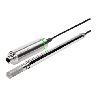
Vaisala DMP Series User Manual (92 pages)
Indigo-compatible dew point and temperature probes
Brand:
Vaisala
| Category:
Measuring Instruments
| Size: 1.33 MB
Table of Contents
Table of Contents
3
1 About this Document
9
Version Information
9
Table Document Versions (English)
9
Related Manuals
10
Documentation Conventions
11
Table 2 Related Manuals
11
Trademarks
12
2 Product Overview
13
Probe Structure
13
Basic Features and Options
13
Figure Probe Parts
13
Output Parameters
14
Table 3 Availability of Output Parameters
14
Additional Features with Indigo Transmitters
15
Safety
15
ESD Protection
16
Regulatory Statements
16
FCC Part 15 Compliance Statement
16
Canada ICES-3 / NMB-3 Compliance Statement
17
3 Functional Description
18
DRYCAP® Technology
18
DRYCAP® Sensor Models in DMP Series Probes
18
Autocalibration
18
Table 4 Drycapâ Sensor Models in DMP Series Probes
18
Sensor Purge
19
Condensation Prevention Functions
19
Environmental Compensation
20
Filtering Factor
21
4 Installation
22
Figure 2 Example Installation
22
DMP5 Probe
23
Figure 3 DMP5 Dimensions
23
Installing with Mounting Flange 210696
24
DMP6 Probe
25
Figure 4 DMP6 Probe Dimensions
25
Figure 5 Cooling Set DMP246CS Dimensions
25
Figure 6 Operating Range of DMP6 Probe Head
26
Figure 7 DMP246CS Cooling Set Mounting Flange
27
Installing Probe Head with Cooling Set DMP246CS
27
Figure 8 DMP246CS Cooling Set Without Mounting Flange
28
Cooling Set Installation Example
29
Figure 9 Example Installation with Cooling Set DMP246CS
29
DMP7 Probe
30
Pressure-Tight Swagelok Installation Kit
30
Figure 10 DMP7 Dimensions
30
Figure 11 DMP7 Installation to Pipeline Using a Swagelok Installation Kit
31
DMP8 Probe
32
Figure 12 DMP8 Dimensions
32
Figure 13 DMP8 Probe Head
33
Figure 14 Sealing of Fitting Body into Process
33
DMT242SC Sampling Cell
34
Tightening the Clasp Nut
34
DMT242SC2 Sampling Cell with Swagelok Connectors
35
Figure 15 Sampling Cells DMT242SC2 (Left) and DMT242SC (Right)
35
Wiring
36
Figure 16 M12 5-Pin A-Coded Male Connector Pinout
36
Figure 17 RS-485 Wiring
36
Configuring Environmental Compensations
37
5 Configuration with Insight Software
38
Vaisala Insight Software
38
Connecting to Insight Software
38
Configuration Options
39
Figure 18 Connecting Probe to Insight Using Indigo USB Adapter
39
Diagnostics in Insight
40
Figure 19 DMP5 in Insight Software
40
Figure 20 DMP5 Diagnostics in Insight (Advanced Mode)
41
6 Using Probe with Indigo Transmitters
42
Connecting Probe to Indigo200 Series Transmitters
42
Connecting Probe to Indigo300 Transmitter
43
Figure 21 Connecting Probe to Indigo200 Series Transmitter
43
Connecting Probes to Indigo500 Series Transmitters
44
Figure 22 Connecting Probe to Indigo300 Transmitter
44
Figure 23 Connecting Probes to Indigo500 Transmitter
45
7 Using Probe with Indigo80 Handheld Indicator
46
Indigo80 Handheld Indicator
46
Figure 24 Indigo80 Handheld Indicator
46
Figure 25 Indigo80 Keypad
47
Figure 26 Indigo80 Main Menu
47
Indigo80 Keypad
47
Indigo80 Main Menu
47
Probe Compatibility
47
Connecting Probes to Indigo80
48
Figure 27 Connecting Probes to Indigo80
48
Configuring Probe Features with Indigo80 Handheld Indicator
49
Example of Configuring Filtering Factor with Indigo80 Handheld Indicator
50
Configuring Environment Settings with Indigo80 Handheld Indicator
51
8 Maintenance
53
Cleaning the Probe
53
Changing the Probe Filter
53
Calibration and Adjustment
54
9 Troubleshooting
55
Problem Situations
55
Error Messages
55
Table 5 Troubleshooting Table
55
Restoring Factory Default Settings with Insight Software
57
Restoring Factory Default Settings with Indigo80 Handheld Indicator
58
10 Technical Data
59
DMP5 Specifications
59
Table 6 DMP5 Measurement Performance
59
Figure 28 DMP5 Dew Point Accuracy Vs. Measurement Conditions
60
Table 7 DMP5 Operating Environment
60
Table 8 DMP5 Inputs and Outputs
60
DMP6 Specifications
61
Figure 29 DMP5 Dimensions
61
Table 9 DMP5 Mechanical Specifications
61
Table 10 DMP6 Measurement Performance
61
Table 11 DMP6 Operating Environment
62
Figure 30 Operating Range of DMP6 Probe Head
63
Table 12 DMP6 Inputs and Outputs
63
Table 13 DMP6 Mechanical Specifications
63
Figure 31 DMP6 Dimensions with Cooling Set DMP246CS
64
Figure 32 DMP6 Probe Dimensions
65
Figure 33 Cooling Set DMP246CS Dimensions
65
DMP7 Specifications
66
Table 14 DMP7 Measurement Performance
66
Figure 34 DMP7 Dew Point Accuracy Vs. Measurement Conditions
67
Table 15 DMP7 Operating Environment
67
Table 16 DMP7 Inputs and Outputs
67
DMP8 Specifications
68
Figure 35 DMP7 Dimensions
68
Table 17 DMP7 Mechanical Specifications
68
Table 18 DMP8 Measurement Performance
68
Figure 36 DMP8 Dew Point Accuracy Vs. Measurement Conditions
69
Table 19 DMP8 Operating Environment
70
Table 20 DMP8 Inputs and Outputs
70
Table 21 DMP8 Mechanical Specifications
70
Accessories and Spare Parts
71
Figure 37 DMP8 Dimensions
71
Table 22 Connection Cables
71
Table 23 DMP5 Accessories
72
Table 24 DMP5 Spare Parts
72
Table 25 DMP6 Accessories
72
Table 26 DMP6 Spare Parts
72
Table 27 DMP7 Accessories
73
Table 28 DMP7 Spare Parts
73
Table 29 DMP8 Accessories
73
Table 30 DMP8 Spare Parts
73
Appendix A: Modbus Reference
75
Default Communication Settings
75
Function Codes
75
Data Encoding
75
Table 31 Default Modbus Serial Communication Settings
75
Table 32 Modbus Function Codes
75
16-Bit Integer Format
76
32-Bit Floating Point or 32-Bit Integer Format
76
Table 33 Interpretation of 16-Bit Signed Integer Values
76
Modbus Registers
77
Measurement Data Registers
77
Table 34 Floating Point Measurement Data Registers (Read-Only)
77
Table 35 Integer Measurement Data Registers (Read-Only)
78
Diagnostic Data Registers
79
Configuration Registers
79
Table 36 Floating Point Diagnostic Data Registers (Read-Only)
79
Table 37 Integer Diagnostic Data Registers (Read-Only)
79
Table 38 Modbus Configuration Data Registers (Writable)
79
Status Registers
81
Table 39 Modbus Status Data Registers (Read-Only)
81
Table 40 Error Codes in Register 0203 Hex
82
Test Value Registers
83
Device Identification Objects
83
Table 41 Modbus Test Registers (Read-Only)
83
Table 42 Device Identification Objects
83
Exception Responses
84
Table 43 Modbus Exception Responses
84
Advertisement
Advertisement
Related Products
Vaisala DRYCAP DM70
Vaisala DEWCAP DM500
Vaisala DMP5
Vaisala DMP6
Vaisala DMP7
Vaisala DMP8
Vaisala GroundCast DRS611
Vaisala DMP80 Series
Vaisala DMP80A
Vaisala DMP80B
Vaisala Categories
Transmitter
Measuring Instruments
Accessories
Test Equipment
Weather Station
More Vaisala Manuals
Login
Sign In
OR
Sign in with Facebook
Sign in with Google
Upload manual
Upload from disk
Upload from URL