Table of Contents
Advertisement
Quick Links
Advertisement
Table of Contents

Related Manuals for Vaisala DRYCAP DM70


Summary of Contents for Vaisala DRYCAP DM70
- Page 1 USER'S GUIDE Vaisala DRYCAP® Hand-Held Dewpoint Meter DM70 M010091EN-F...
- Page 2 The contents are subject to change without prior notice. Please observe that this manual does not create any legally binding obligations for Vaisala towards the customer or end user. All legally binding commitments and agreements are included exclusively in the applicable supply contract or Conditions of...
-
Page 3: Table Of Contents
Feedback................... 6 Recycling .................. 7 Trademarks ................7 Warranty..................8 CHAPTER 2 PRODUCT OVERVIEW.................. 9 ® Introduction to Vaisala DRYCAP Hand-Held Dewpoint Meter DM70 ................9 Basic Features and Options..........10 Parts Description..............11 CHAPTER 3 PREPARATIONS BEFORE USE..............13 Installing and Removing the Battery Pack ...... - Page 4 USER'S GUIDE____________________________________________________________________ Auto-Calibration..............27 Automatic Auto-Calibration..........27 Turning off Automatic Auto-Calibration ......28 Manual Auto-Calibration..........28 Sensor Purge...............29 Turning on/off Automatic Sensor Purge ......30 Changing Automatic Sensor Purge Interval ....30 Manual Sensor Purge.............31 Calibrate Transmitters (used only with DMP248)....32 Recording/Viewing Menu............32 Recording Data..............32 Stopping Recording............34 View Recorded Data ............34 Memory Status ..............34 Clear Data Memory .............35...
- Page 5 Temperature Adjustment of DMT340 Series Using DM70 . 75 To Same as T .............. 76 I/II 1-Point Adjustment............76 2-Point Adjustment............77 Vaisala Service Centers............78 CHAPTER 10 DE-COMMISSIONING, DISMANTLING, AND DISPOSAL ......79 CHAPTER 11 TECHNICAL SPECIFICATIONS..............81 Measured Variables..............81 Dewpoint Temperature............
- Page 6 USER'S GUIDE____________________________________________________________________ MI70 Indicator..............85 Indicator General............85 Battery Pack ..............86 ® DMP74 Probe + MI70 Indicator = Vaisala DRYCAP DM70 Hand-Held Dewpoint Meter ..........86 General................86 Electromagnetic Compatibility........87 Sampling Cells ...............87 DMT242SC Sampling Cell ........87 DMT242SC2 Sampling Cell with Swagelok Connectors ..............87 DSC74 Sampling Cell for Pressurized Gases...87...
- Page 7 ________________________________________________________________________________ List of Tables Table 1 Measurement Intervals and Maximum Recording Times..33 Table 2 List of Accessories ..............89 VAISALA ________________________________________________________________________ 5...
-
Page 8: Chapter 1 General Information
NOTE Note highlights important information on using the product. Feedback Vaisala Customer Documentation Team welcomes your comments and suggestions on the quality and usefulness of this publication. If you find errors or have other suggestions for improvement, please indicate the chapter, section, and page number. You can send comments to us by e-mail: manuals@vaisala.com... -
Page 9: Recycling
Do not dispose of with regular household refuse. Trademarks ® DRYCAP is a registered trademark of Vaisala. Microsoft , Windows , and Windows NT are registered trademarks of Microsoft Corporation in the United States and/or other countries. VAISALA ________________________________________________________________________ 7... -
Page 10: Warranty
Products should Vaisala so require, be sent to the works supplied hereunder, which obligations of Vaisala or to such other place as Vaisala may liabilities are hereby expressly cancelled and indicate in writing, freight and insurance waived. Vaisala's liability... -
Page 11: Chapter 2 Product Overview
Chapter 2 __________________________________________________________ Product Overview CHAPTER 2 PRODUCT OVERVIEW ® Introduction to Vaisala DRYCAP Hand-Held Dewpoint Meter DM70 DM70 measures dewpoint temperature accurately in a measurement range from -60 C up to +60 C depending on the probe version. ®... -
Page 12: Basic Features And Options
USER'S GUIDE____________________________________________________________________ DM70 consists of two main units: the MI70 indicator and DMP74 probe, versions A, B, or C. DM70 can be used with the optional sampling cell to measure process dewpoint. With DSS70A, DM70 forms a part of a complete portable sampling system for measuring process dewpoint. -
Page 13: Parts Description
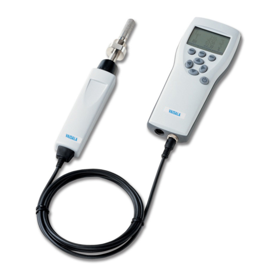
Chapter 2 __________________________________________________________ Product Overview Parts Description 0403-031 Figure 1 Hand-Held Dewpoint Meter DM70 The following numbers refer to Figure 1 above. MI70 indicator DMP74 probe Sampling cell DSC74 (optional) Calibration button Recharger connector Connector ports for probes and cables VAISALA _______________________________________________________________________ 11... - Page 14 USER'S GUIDE____________________________________________________________________ This page intentionally left blank. 12 __________________________________________________________________ M010091EN-F...
-
Page 15: Preparations Before Use
0403-032 Figure 2 Installing the Battery Pack Connect the black connector of the new battery pack. Make sure the red and black wires are on the upper edge of the connector. VAISALA _______________________________________________________________________ 13... -
Page 16: Charging The Battery Pack
USER'S GUIDE____________________________________________________________________ Do not push the connector with any conducting material. See Figure 2 on page 13. NOTE If you have previously used alkaline batteries, remove the metal contact before installing the battery pack. Replace the battery pack, close the back plate, and tighten the screw. -
Page 17: Buttons And Navigation
Press any of the arrow buttons and open a menu by pressing Open. Select Settings using the buttons and press Select User interface and press Select Language and press Set. Select the language using the buttons. Confirm the selection by pressing Select. VAISALA _______________________________________________________________________ 15... - Page 18 USER'S GUIDE____________________________________________________________________ If you want to set the date at this point, return to the Settings menu by pressing The language can be selected also later. See section Language on NOTE page 37. To change the date, select Date and press Set.
-
Page 19: Dewpoint Measurement
Avoid PVC or nylon tubes. Measuring If you start DM70 for the first time, see section Preparations Before Use on page 13. Otherwise, follow the instructions below. Connect the probe to the MI70 indicator. Press the Power On/Off button. VAISALA _______________________________________________________________________ 17... - Page 20 USER'S GUIDE____________________________________________________________________ Install the probe to the measuring position. If you are measuring in pressurized processes, see section Connection to Pressurized Processes Using the DSC74 Sampling Cell on page 52. When using other sampling cells than DSC74, make sure that the threads are compatible with the probe threads (G ½"...
-
Page 21: Chapter 5 User Interface
This chapter contains information that is needed to operate this product. Basic Display When DM70 is turned on, the display shown in Figure 4 below appears. 0403-034 Figure 4 Basic Display The following numbers refer to Figure 4 above. The state of the battery. Pressure settings. VAISALA _______________________________________________________________________ 19... -
Page 22: Menus
USER'S GUIDE____________________________________________________________________ Selected quantities. Up to three of the following quantities can be selected at a time: dewpoint (T ), relative humidity (RH), absolute humidity (a), mixing ratio (x), parts per million (H O), temperature (T). The Graphic shortcut button changes the display into a curve mode. -
Page 23: Display Menu
You can select 1 ... 3 display quantities at a time. The unit of quantities (T , or T) can be selected between C or F. The default is C. To select a quantity, do the following: VAISALA _______________________________________________________________________ 21... -
Page 24: Rounding
USER'S GUIDE____________________________________________________________________ Open the menu by pressing Open. Select Display and press Select Quantities and units and then press To select a quantity, move on the desired quantity using the arrow buttons and then press Select. To change the unit, move on the desired quantity using the arrow buttons and then press Unit ( C or F). -
Page 25: Hold/Save
To view the recording time stamps, press Times. To return to the basic display, press Exit. Graphic History The graphical display shows the measurements as a curve. From the curve, you can examine the data trend and history of the last minutes. VAISALA _______________________________________________________________________ 23... -
Page 26: Functions Menu
USER'S GUIDE____________________________________________________________________ The graphical display shows the curve of the uppermost quantity shown in the basic display. Open the menu by pressing Open. Select Display and press To go to the Graphical history display, select Graphic history and press Show. To get the statistical info on the graph area (minimum, maximum, and average values), press Info. - Page 27 When the alarm level is reached, you can stop the alarm by pressing OK. To reactivate the alarm, press Yes. To completely stop the alarm, press NOTE The alarm does not work when the device is turned off. VAISALA _______________________________________________________________________ 25...
-
Page 28: Analog Output
USER'S GUIDE____________________________________________________________________ Analog Output Selecting and Scaling the Analog Output 0403-052 Figure 8 Analog Output To get analog measurement data, an analog signal cable is needed (see section Accessories on page 89). Connect the signal cable connector of the analog output to the base connector of the indicator. -
Page 29: Auto-Calibration
10 ºC. However, if there are no changes in the conditions, the calibration will take place at an interval of one hour or at least, after one hour from the last auto-calibration. VAISALA _______________________________________________________________________ 27... -
Page 30: Turning Off Automatic Auto-Calibration
USER'S GUIDE____________________________________________________________________ Turning off Automatic Auto-Calibration If the automatic auto-calibration is turned off, the auto-calibration NOTE should be started when starting measuring after the probe has not been used for a while and always at least once every hour. The automatic auto-calibration can be turned off as follows: Open the menu by pressing Open. -
Page 31: Sensor Purge
Sensor purge is an automatic procedure, in which the sensor is dried. Thus, the sensor will response very fast when installing the probe from an ambient to a dry gas. This will also ensure together with auto- calibration the best measurement accuracy and long-term stability. VAISALA _______________________________________________________________________ 29... -
Page 32: Turning On/Off Automatic Sensor Purge
USER'S GUIDE____________________________________________________________________ The purge is performed automatically if humidity changes significantly or quickly and if the dewpoint is low enough. As a default, the automatic sensor purge is turned on automatically in DM70. It is recommended not to turn it off. The automatic sensor purge can also be started manually, which is necessary if the purge has not been performed during the last 24 hours. -
Page 33: Manual Sensor Purge
15 seconds to inform of the time required to complete the purge. The purge symbol also appears in the upper left corner of the display. See Figure 10 on page 31. 0403-044 Figure 10 Sensor Purge Displays VAISALA _______________________________________________________________________ 31... -
Page 34: Calibrate Transmitters (Used Only With Dmp248)
USER'S GUIDE____________________________________________________________________ You can also change one of the shortcut keys to refer to the sensor purge. See section Program Shortcut Keys on page 38. Calibrate Transmitters (used only with DMP248) In this menu, you can set the baud rate, serial format, and start calibration. - Page 35 The bar indicates the amount of recorded data. CAUTION Do not disconnect the probe when the data recording is on, even if the indicator is turned off. This may cause loss of recorded data. VAISALA _______________________________________________________________________ 33...
-
Page 36: Stopping Recording
USER'S GUIDE____________________________________________________________________ Stopping Recording To stop recording, press Record. Select Record data and press Then select Start/Stop recording and press Stop. To view the recorded file, select Show. View Recorded Data Open the menu by pressing Open. Select Recording/Viewing and press Select View recorded data and press Select the file you want to view and press . -
Page 37: Clear Data Memory
Transferring Recorded Data to PC The recorded data can be transferred to a PC using the MI70 Link program. The MI70 Link program can be ordered from Vaisala, see section Accessories on page 107. You can examine the recorded data easily in the Microsoft Windows®... -
Page 38: Environment Menu
USER'S GUIDE____________________________________________________________________ Environment Menu Pressure Settings In pressurized environments, the actual process pressure value must be set for DM70. The pressure can be given in the following units: Gauge pressure is given in the unit of bar. It barg: indicates the pressure difference between the normal atmospheric pressure and the actual process pressure. -
Page 39: Settings Menu
Go to the Language selection menu by pressing first then the button in the middle. Then press , then , then again and finally press again button in the middle. Reselect the language. VAISALA _______________________________________________________________________ 37... -
Page 40: Automatic Power Off
USER'S GUIDE____________________________________________________________________ Automatic Power Off As a default, the power in DM70 is automatically turned off after 15 minutes of inactivity. This also saves the battery. The inactivity settings can be changed to 60 minutes or completely turned off. See the instructions below: Open the menu by pressing Open. -
Page 41: Button Tones And Backlight
The default date format is day.month.year, for example, 25.4.2004. The date format can be changed to month.day.year. or year.month.day. For correct time and date in the recorded data files, follow the instructions below: Open the menu by pressing Open. Select Settings and press VAISALA _______________________________________________________________________ 39... -
Page 42: Measurement Settings
USER'S GUIDE____________________________________________________________________ Select Date and time and press For the desired date, select Date and then press Set. Use the arrow buttons to change the date. Confirm the selection by pressing Select. To change the date format, select from the alternatives and press Select. -
Page 43: Purge Interval
Select Device information and press Show. The first display gives the information on the MI70 indicator. For details on the probe, press More and then press See Figure 18 below. To return to the basic display, press Exit. VAISALA _______________________________________________________________________ 41... -
Page 44: Factory Settings
USER'S GUIDE____________________________________________________________________ 0403-041 Figure 18 Indicator and Probe Information The following numbers refer to Figure 18 above. Software version of the MI70 indicator Serial number of the MI70 indicator Probe type Software version of the probe Serial number of the probe Factory Settings The factory settings can be restored to clear all the changed settings and data memory of the indicator. -
Page 45: Field Calibration Check Of Fixed Transmitters
FIELD CALIBRATION CHECK OF FIXED TRANSMITTERS To compare measurement readings or to read the output of a fixed transmitter directly on the DM70 display, connect DM70 to a fixed Vaisala transmitter using the connection cable accessories. ® Vaisala DRYCAP Dewpoint and Temperature Transmitter Series DMT340 can be adjusted in laboratory conditions using DM70 as a reference. -
Page 46: Field Calibration Check Of Dmp248
However, in applications where optimum accuracy is essential, it is recommended to send the DMT340/DMT242/DMT142 transmitter to Vaisala (see section Vaisala Service Centers on page 78) when the difference is considered significant. Press the Power On/Off button. Disconnect the connection cable. -
Page 47: Figure 19 Calibrate Transmitters Message
Check the environment settings of the DM70 probe, if needed. Press Yes or The measurement value of DMP248 is shown on the upper row and the value of DM70 on the second row. The third row shows the difference between the measurements of DMP248 and DM70. VAISALA _______________________________________________________________________ 45... - Page 48 However, in applications where best possible accuracy is essential, it is recommended to send the DMP248 transmitter to Vaisala (see section Vaisala Service Centers on page 78) if the difference is considered significant. To return to the basic display, press Exit.
-
Page 49: Sampling From Processes
Use the DMT242SC sampling cell when only the body (thread 3/8"G and 1/4"G) of the main sampling cell is needed. Use the DMT242SC2 sampling cell with the welded Swagelok connectors. This is ideal for sampling in a 1/4" pipeline. VAISALA _______________________________________________________________________ 47... -
Page 50: Sampling Cells
USER'S GUIDE____________________________________________________________________ Sampling Cells DSC74 - sampling cell with a leakage screw, thread 3/8"G - quick coupling, type NIP08, type D - thread adapter, type 3/8" - 1/4"G - thread adapter, type 3/8" - 1/2"G (for DMP248 and DMT242 fittings) 0403-047 Figure 20 DSC74 Sampling Cell with the Adapters... -
Page 51: Dsc74B
- sampling cell, thread 3/8"G - connection part with a needle valve and an integrated leakage screw - Reducing Nipple (thread adapter), 3/8"G - 1/2"G - Reducing Adapter (thread adapter), 3/8"G - 1/4"G - diffusion coil (for measurements in atmospheric pressure) VAISALA _______________________________________________________________________ 49... -
Page 52: Figure 22 Default Assembly Of Dsc74C
USER'S GUIDE____________________________________________________________________ 0403-112 Figure 22 Default Assembly of DSC74C The following numbers refer to Figure 22 above. Gas goes in. Also the coil can be used here. Gas comes out Coil Valve 50 __________________________________________________________________ M010091EN-F... -
Page 53: Figure 23 Alternative Assembly Of Dsc74C For Tight Spaces
The following numbers refer to Figure 23 above. Gas comes out Coil Thread, max. size 7 mm Gas goes in Valve The thread size cannot exceed 7 mm. Use the provided adapter to avoid damage to the probe. VAISALA _______________________________________________________________________ 51... -
Page 54: Dmt242Sc
DMT242SC and DMT242SC2 Sampling Cells Connection to Pressurized Processes Using the DSC74 Sampling Cell DSC74 is a Vaisala sampling cell for connecting DM70 to the pressurized processes (See section Accessories on page 89). With DSC74B and DSC74C measuring can be done in overpressure or atmospheric pressure. - Page 55 Tighten the fitting with a fork spanner. Connect the sample cell to the process fittings. Seal the fitting with the PTFE thread seal tape. Install the gasket (delivered with the probe) to the nut of probe thread. VAISALA _______________________________________________________________________ 53...
-
Page 56: Dss70A Sampling System
USER'S GUIDE____________________________________________________________________ Set the probe into the sample cell. Tighten the probe by turning it from the thread nut. Do not tighten the probe from the handle. If the sample cell is installed correctly, there is no leakage in the connections. -
Page 57: Dss70A Sampling Procedure
Chapter 7 ____________________________________________________Sampling from Processes The DSS70A sampling system can be ordered from Vaisala separately ® or in connection with the Vaisala DRYCAP Hand-Held Dewpoint Meter DM70. 0403-048 Figure 25 DM70 with the Case The following numbers refer to Figure 25 on page 55. -
Page 58: Dss70A Maintenance
USER'S GUIDE____________________________________________________________________ (1.2 ... 20 bar), detach the flexible tube from the flowmeter. See Figure 25 on page 55. Remove the inlet/outlet plugs. Insert the 1/4" tubing into the IN fitting. Tighten the nut 11/4 turns with an open-ended, 14-mm spanner to make a gas-tight fitting. -
Page 59: Changing The Battery
MI70 recharger adapter to the recharger socket on top of MI70 and recharge DSS70A as described above. Changing the Battery Replacement batteries can be ordered from Vaisala (see section Accessories on page 89). The battery is fitted underneath the sampling system. To change the battery, lift the sampling system from the briefcase. -
Page 60: Figure 27 Sampling System Upside Down
USER'S GUIDE____________________________________________________________________ Turn the sampling system upside down. See Figure 27 below. 0403-050 Figure 27 Sampling System Upside Down The following numbers refer to Figure 27 above. Battery Battery wires Nut of the sample cell Detach the battery wires. Remove the old battery by pulling it up. -
Page 61: Changing The Filter
The filter may need to be changed after several hundreds of hours or after years. A dry filter may cause increased response times. A new filter can be ordered from Vaisala (see section Accessories on page 89). To change the filter, lift the sampling system out of the briefcase. -
Page 62: Changing The Fuses
USER'S GUIDE____________________________________________________________________ Changing the Fuses Press down the fuse button and simultaneously turn it. Replace the old fuse with a new one of same type and rating (glass tube fuse 5 x 20 mm T 2 A/250 VAC). Put the fuse button back into place by pressing and turning it. -
Page 63: Measuring Moisture In Sf
Figure 29 on page 62. When measurement is done in the GIE pressure, the structure of DSC74B eliminates the adverse effect of pressure fluctuation caused by the collection system. VAISALA _______________________________________________________________________ 61... -
Page 64: Operating Environment
USER'S GUIDE____________________________________________________________________ 0405-011 Figure 29 Gas Collection Option The following numbers refer to Figure 29 above. Gas from GIE Gas to the collecting system Operating Environment A typical dewpoint of pure SF is usually around -60 °C. The recommendations for the moisture limit of the equipment insulated with gas (GIE) vary between 70 ... -
Page 65: Figure 30 Removing The Leak Screw
For SF , the molecular weight is 146.06, and the conversion between ppm and ppm is the following: = ppm / 8.1 DM70 is able to show the ppm and ppm values for moisture. VAISALA _______________________________________________________________________ 63... - Page 66 USER'S GUIDE____________________________________________________________________ This page intentionally left blank. 64 __________________________________________________________________ M010091EN-F...
-
Page 67: Calibration, Adjustment, And Maintenance
The device can be sent to a Vaisala Service Center for calibration and adjustment, see contact information in section Vaisala Service Centers on page 78. -
Page 68: Adjusting Dm70
Device Information on page 41). Adjusting DMT340 Series Transmitters Using DM70 as Reference or Terminal ® Vaisala DRYCAP Dewpoint and Temperature Transmitter Series DMT340 can be adjusted using a correctly adjusted DM70 as a reference dewpoint meter. Note that dewpoint adjustment should be carried out in laboratory conditions and not in the field. -
Page 69: Adjusting Dewpoint
When pressing the button, the indicator switches into the adjustment mode. To start adjusting, press Then select RH and press Select. To check the environmental settings, press Yes. To continue without checking the settings, press VAISALA _______________________________________________________________________ 67... -
Page 70: Two-Point Relative Humidity Adjustment Of Dmt340 Series Transmitters Using Dm70
USER'S GUIDE____________________________________________________________________ To select the adjustment method, press Adjust. Select 2-point adjustment and press Select. Then press OK to continue. Set the probe to a lower reference value of relative humidity You can follow the stabilization from the graph display by pressing Graph. - Page 71 Set the probe to a higher reference value of relative humidity When the reading has stabilized, press Ready. You can follow the stabilization from the graph display by pressing Graph. Use arrow buttons to give the higher reference value of relative humidity. Then press VAISALA _______________________________________________________________________ 69...
-
Page 72: Adjusting Dewpoint T
USER'S GUIDE____________________________________________________________________ Confirm the adjustment by pressing Yes. If you press the adjustment display returns and no changes are made. Now the adjustment is completed. To exit the adjustment mode, press Back. To return to the basic display, press Exit. 1) If there is a temperature difference between the generated reference and the probe temperature, relative humidity must be calculated to correspond to the temperature of the probe. -
Page 73: T D/F Adjustment Of Dmt340 Series Transmitters Using Dm70
Turn off DM70. Connect the cable 211339 between DMT340 (service port) and DM70 (connector I or II). Turn on both the devices. Set the probe to the reference condition. Follow the stabilization from the graphic display by pressing VAISALA _______________________________________________________________________ 71... -
Page 74: To Same As T
USER'S GUIDE____________________________________________________________________ Graph. The minimum recommended stabilization time for this critical adjustment is 5 hours. Perform the manual purge if necessary. Press the ADJ button on the DMT340 motherboard to enable the adjustment mode. From the list of parameters, select T d/f I/II You are prompted to check the settings, make sure that the pressure units of DM70 and DMT340 are the same. -
Page 75: 1-Point Adjustment
Place the screw back onto the calibration button. To seal the calibration, attach a sticker on the calibration button. NOTE Several AutoCals can be necessary after this adjustment has been performed until the transmitter reaches full accuracy. VAISALA _______________________________________________________________________ 73... -
Page 76: Adjusting Temperature
USER'S GUIDE____________________________________________________________________ Adjusting Temperature Temperature Adjustment of DM70 The temperature adjustment can be done using the one-point or two- point adjustment. The one-point adjustment should be done within the temperature range in which the device is most often used. To go to the adjustment mode, do the following: Press the Calibration button of the probe handle (see number 4 in Figure 1 on page 11) using a tool with a thin, sharp point, for example, a small screwdriver. -
Page 77: Two-Point Adjustment
Turn off DM70. Connect the cable 211339 between DMT340 (service port) and DM70 (connector I or II). Turn on both the devices. Press the ADJ button on the DMT340 motherboard to enable the adjustment mode. VAISALA _______________________________________________________________________ 75... -
Page 78: To Same As T
USER'S GUIDE____________________________________________________________________ From the list of parameters, select T I/II At this point you need to select the adjustment method. If the reference probe is connected, two options are displayed: To same as T , 1-point adjustment or 2-point adjustment. I/II You are prompted to check the settings, make sure that the pressure units of DM70 and DMT340 are the same. -
Page 79: 2-Point Adjustment
The adjustment has been completed. NOTE If the difference between the two references is less than 30 ˚C, the adjustment cannot be done. To exit the adjustment mode, press Back. To return to the basic display, press Exit. VAISALA _______________________________________________________________________ 77... -
Page 80: Vaisala Service Centers
USER'S GUIDE____________________________________________________________________ Vaisala Service Centers 78 __________________________________________________________________ M010091EN-F... -
Page 81: De-Commissioning, Dismantling, And Disposal
Installing and Removing the on page 13 (MI70) and in section Battery Pack Changing on page 57 (DSS70A). the Battery 3. Dismantled parts must be separated according to the materials and disposed of according to the local laws and regulations. VAISALA _______________________________________________________________________ 79... - Page 82 USER'S GUIDE____________________________________________________________________ This page intentionally left blank. 80 __________________________________________________________________ M010091EN-F...
-
Page 83: Technical Specifications
(dewpoint measured in pressure, calculated to 1 atm dewpoint value) DMP74A -64 ... +60 ˚C (-83 ... 140 ˚F) DMP74B -80 ... +20 ˚C (-112 ... 68 ˚F) DMP74C -72 ... +20 ˚C (-98 ... 68 ˚F) VAISALA _______________________________________________________________________ 81... -
Page 84: Figure 31 Dmp74A Accuracy
USER'S GUIDE____________________________________________________________________ 0602-003 Figure 31 DMP74A Accuracy 0602-004 Figure 32 DMP74B Accuracy 0602-005 Figure 33 DMP74C Accuracy 82 __________________________________________________________________ M010091EN-F... -
Page 85: Temperature
40 ... 200000 ppm DMP74B/C 10 ... 20000 ppm Accuracy at +20 ˚C (+68 ˚F) < 40 ppm ± (0.5 ppm + 25.4 % of reading) > 40 ppm ± (7.3 ppm + 8.3 % of reading) VAISALA _______________________________________________________________________ 83... -
Page 86: Absolute Humidity (Dmp74A Probe Recommended)
USER'S GUIDE____________________________________________________________________ Absolute Humidity (DMP74A Probe Recommended) Measurement range (typical) 0.5 ... 100 g/m (0.2 ... 40 gr/ft Accuracy ± (0.2 g/m + 10 % of reading) ± (0.1 gr/ft + 10 % of reading) Mixing Ratio (DMP74A Probe Recommended) Measurement range (typical) 0.2 ... -
Page 87: Probe General
Display LCD with backlight Graphic trend display of any quantity Character height up to 16 Probe inputs 1 or 2 Power supply Rechargeable NIMH battery pack with AC power or 4 x AA size alkalines, type IEC VAISALA _______________________________________________________________________ 85... -
Page 88: Battery Pack
30 days Power consumption during 10 W max charge Charging time 4 hours DMP74 Probe + MI70 Indicator = ® Vaisala DRYCAP DM70 Hand-Held Dewpoint Meter General Storage temperature -40 ... +70 ˚C (-40 ... +158 ˚F) Storage humidity range 0 ... -
Page 89: Electromagnetic Compatibility
1 MPa, 10 bar , 145 psi Material Stainless steel AISI316 Weight 300 g DSC74B Two-Pressure Sampling Cell Inlet/outlet thread ISO G 3/8"/G 3/8" Flow adjustment Manually operated Pressure limit 1 MPa, 10 bar , 145 psi VAISALA _______________________________________________________________________ 87... -
Page 90: Dsc74C
USER'S GUIDE____________________________________________________________________ Material Stainless steel AISI316 Weight 390 g DSC74C DSC74C is a sampling cell with DSC74B with DMCOIL cooling/venting coil. DMCOIL Coil pipe size 6 mm Connection to sampling cell With ISO G 1/4" and G 3/8" thread adapter Weight 130 g DSS70A Sampling System... -
Page 91: Accessories
DSS70BAT Service kit for DSC74 (all versions) DSC74SERVICEKIT PC Connection tools MI70 Link software interface kit including a 219687 USB instrument cable for MI70 MI70 Link software interface kit including a MI70LINK serial connection cable for MI70 VAISALA _______________________________________________________________________ 89... -
Page 92: Dimensions
USER'S GUIDE____________________________________________________________________ Dimensions 0403-055 Figure 34 Dimensions in Millimeters (Inches) Warranty 90 __________________________________________________________________ M010091EN-F... - Page 93 *M010091EN*...
Need help?
Do you have a question about the DRYCAP DM70 and is the answer not in the manual?
Questions and answers