
Subscribe to Our Youtube Channel
Related Manuals for Daktronics Sportsound SSN-150


Summary of Contents for Daktronics Sportsound SSN-150
- Page 1 SSN-150 INDOOR AUDIO SYSTEM WITH SSR-WR CONTROL RACK INSTALLATION MANUAL P1756 DD3953030 Rev 05 19 March 2024 201 Daktronics Drive Brookings, SD 57006-5128 www.daktronics.com/support 800.325.8766...
- Page 2 Daktronics trademarks are property of Daktronics, Inc. All other trademarks are property of their respective companies.
-
Page 3: Table Of Contents
Table of Contents Introduction ���������������������������������������������������������������������������������������������������������������������������1 Important Safeguards ..........................1 Resources ..............................1 Daktronics Nomenclature ........................2 Sound System Components ������������������������������������������������������������������������������������������������3 Equipment Overview ...........................3 Sound Cabinet ............................3 Grille���������������������������������������������������������������������������������������������������������������������������������������������������3 Drivers ������������������������������������������������������������������������������������������������������������������������������������������������3 Control Enclosure..........................3 Audio Mixer ���������������������������������������������������������������������������������������������������������������������������������������4 CD/Media Player ������������������������������������������������������������������������������������������������������������������������������5 Wireless Microphone System (Optional) ����������������������������������������������������������������������������������������5 High Gain Antenna Kit (Optional) ���������������������������������������������������������������������������������������������������6 USB Audio Interface �������������������������������������������������������������������������������������������������������������������������6... - Page 4 Sound Cabinet Components ���������������������������������������������������������������������������������������������������������27 Control Components ����������������������������������������������������������������������������������������������������������������������27 Optional Components �������������������������������������������������������������������������������������������������������������������28 Mesh Replacement ..........................29 Daktronics Exchange and Repair & Return Programs ����������������������������������������������������31 Exchange Program ..........................31 Repair & Return Program ........................32 Daktronics Warranty & Limitation of Liability ...................32 A Reference Drawings �����������������������������������������������������������������������������������������������������������33 Supplementary Manuals ����������������������������������������������������������������������������������������������������41...
-
Page 5: Introduction
Reference Drawing: System Riser Diagram ..................DWG-1007804 Daktronics identifies manuals by the DD or ED number located on the cover page. Daktronics has a searchable knowledgebase of common questions and troubleshooting tips: www.daktronics.com/support. -
Page 6: Daktronics Nomenclature
Materials (BOM) for the project. If a component is not found in the Replacement Parts (p�27), use the label to order a replacement. Figure 2: Part Label Refer to Section 7: Daktronics Exchange and Repair & Return Programs (p�31) if replacing or repairing any component. Main Component Labels... -
Page 7: Sound System Components
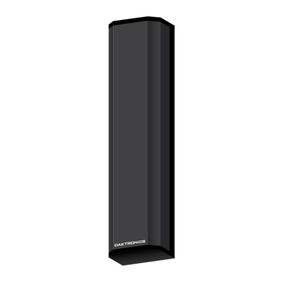
• Signal Cables Sound Cabinet Figure 3 illustrates the Sportsound SSN-150 indoor sound system cabinet. This system features a line array column speaker, plus an additional low frequency driver housed in a protective cabinet 8'-0" (2.44 m) high, 2'-0" (610 mm) wide, and 1'-5" (432 mm) deep. -
Page 8: Audio Mixer
Amplifier Indicators (p.25) All supplementary manuals are listed in Appendix B. Audio Mixer Figure 5: Audio Mixer The Daktronics 1RU Multimedia Mixer shown in Figure 5 features: • Four mic inputs with bass cut for vocal microphones and phantom power •... -
Page 9: Cd/Media Player
CD/Media Player Figure 6: CD/Media Player The TASCAM CD-400U shown in Figure 6 is a professional rack-mount CD/Media Player with flexible file formats and inputs/outputs. Other features include: • MP3, WAV, AAC, and WMA file playback • Support for SD/SDHC cards and USB memory devices •... -
Page 10: High Gain Antenna Kit (Optional)
High Gain Antenna Kit (Optional) The Lectrosonics ALP620 shown in Figure 8 is a directional antenna for increased range and reduced interference. The “gain” of this antenna enables it to receive signals from a greater distance than at typical “whip” type antenna. -
Page 11: Mechanical Installation
Mechanical Installation A qualified technician must install the Sportsound sound system cabinet and control enclosure. Due to the variety of wall materials used in sports facilities, Daktronics cannot anticipate the individual installation needs or provide mounting hardware suitable for every installation. It is the installation contractor’s responsibility to install the proper wall mounting hardware to ensure the cabinet is mounted safely and securely to the wall. -
Page 12: Grille Frame Removal
Refer to Figure 13. Use the lift eyes to lift the sound cabinet to the desired location on the wall. Note: Daktronics assumes no liability for damages resulting from incorrect setup or lifting methods. Eyebolts are intended for lifting only. Do not... -
Page 13: Mounting
Mounting Tools Required: 3/4" socket, hammer drill for pre-drilling hole in wall, DD2670874 The rear of the SSN-150 cabinet has two square cutouts that allow it to hang on two steel clip angles mounted to the wall, 1'-4" (406 mm) apart, with 1/2" hardware. Inside the cabinet toward the bottom, additional 1/2"... -
Page 14: Mounting The Control Enclosure
Mounting the Control Enclosure The backpan of the control enclosure mounts directly on the wall. The orientation of the backpan is determined by which way the rack will swing open. The main rack then is lifted and secured into the backpan. Refer to the Middle Atlantic DWR Series Instruction Sheet shipped with the rack and listed in Appendix B for mounting specifications. -
Page 15: Electrical Installation
Electrical Installation CAUTION – RISK OF ELECTRIC SHOCK: Only qualified individuals should perform power routing and termination to the system. Electrical contractors are responsible for ensuring that all electrical work meets or exceeds local and national codes. Failure to follow installation guidelines will result in audible noise on the sound system and possible damage to internal components. -
Page 16: Power
– must be electrically grounded. Only qualified individuals may perform electrical work, including verification of ground resistance. Daktronics is not responsible for improper grounding or damage incurred as a result of improper grounding. Grounding methods must meet the provisions of all applicable local and national codes. - Page 17 Figure 20: SSN-150 Termination Block 5� Reattach the front grille once wiring terminations and speaker aiming are complete. Refer to Speaker Installation (p�7). Electrical Installation...
-
Page 18: Setup And Operation
4� Use the key switch on the front of the control rack to turn on the system. When shipped from Daktronics, the keys will be stored in the front rack drawer. Note: Rack components are sequenced to power on in the correct order to avoid an audible "pop"... -
Page 19: Mixer Operation
Mixer Operation 1� Ensure all source equipment is turned on and operational. If any optional wireless microphone systems are included, refer Shure Wireless Mic System Operation (p�17) or Electro-Voice Wireless Mic System Operation (p�19). 2� For each channel (input source) in use, verify the green LED is illuminated, and then turn up the knob until the red LED starts to light, and then turn it down by one half to one full number. -
Page 20: Amplifier Presets
Amplifier Presets If there are speech/music intelligibility issues at the venue caused by too much bass, a different amplifier preset may be required. Contact Daktronics for more information. Surge Protector The power sequencer features a 20A breaker as shown in Figure 24. If the breaker trips, press the small button next to the key switch to reset it. -
Page 21: Shure Wireless Mic System Operation
Shure Wireless Mic System Operation Basic instructions are described below. For more information about wireless mic system operation, refer to the Shure QLX-D Wireless System User Guide. Wireless Receiver IR Window Power Figure 25: Wireless Receiver LCD & Controls The wireless receiver unit shown in Figure 25 displays the following information: Power a�... -
Page 22: Wireless Mic And Bodypack Setup
IR Window Power Wireless Mic and Bodypack Setup Power ON/OFF IR Window Power ON/OFF Figure 26: Wireless Mic & Bodypack Controls 1� Open the battery cover. Insert new or fully-charged AA batteries prior to each use, and always have spares on hand. 2�... -
Page 23: Electro-Voice Wireless Mic System Operation
Electro-Voice Wireless Mic System Operation Basic instructions are described below. For more information about wireless mic system operation, refer to the Electro-Voice RE3 UHF Wireless System User Manual. Power Sync Port Figure 27: RE3 Wireless Receiver LCD & Controls The wireless receiver unit shown in Figure 27 displays the following information: a�... -
Page 24: Wireless Mic And Bodypack Sync
Power Sync Port Wireless Mic and Bodypack Sync Sync Port Power & Mute Figure 28: RE3 Wireless Mic & Bodypack Controls 1� Open the battery cover. Insert new or fully-charged AA batteries prior to each use, and always have spares on hand. 2�... -
Page 25: Microphone Best Practices
Microphone Best Practices • Keep handheld microphones 4–6" (102-152 mm) from the mouth (about the width of a hand). “P-pops” are loud sounds created by the release of breath when saying letters like “p” or “b”. To avoid P-pops, keep handheld microphones below the mouth, angled toward the nose at a 45°... -
Page 26: Feedback
Communicate to the referee that they shouldn’t be making announced calls past a certain point on the field. For additional recommendations for reducing wireless microphone dropouts and feedback, refer to the Wireless Mic Best Practices – Shure QLX-D (DD3871886), available online at www.daktronics.com/manuals. Setup and Operation... -
Page 27: Troubleshooting And Replacement Parts
No full-range audio One or more outputs muted Ensure no outputs are muted. Microphones sound muddy; Contact Daktronics to set a Subwoofer set too high too much bass different amplifier preset. Resistance Check Check the resistance (ohms) of the lines with an analog or digital multimeter at the back of the amplifier in the rack and/or at the speaker terminal locations within the speaker cabinet. -
Page 28: Test Tones
* Disconnect the subwoofer from amplifier (CH4 OUT) if possible to ensure you are only listening to the column speaker. If all tones are present, the drivers are connected and operating properly. If any test tones do not play, the driver(s) may need to be replaced. Contact Daktronics. Troubleshooting and Replacement Parts... -
Page 29: Amplifier Indicators
Amplifier Indicators The amplifier in the control enclosure features several LED indicators that are helpful when trying to diagnose issues with the audio system. Refer to Figure 33 and the following descriptions (LED color is in parentheses). FAULT (Red): Indicates channel shutdown to protect •... -
Page 30: Control Rack Troubleshooting
Control Rack Troubleshooting Symptom/Condition Possible Cause Potential Solution Power key switch is in the OFF Flip switch to the ON position. position. No power lights illuminated on rack equipment. Rack is plugged into dead wall Verify the rack is plugged into live receptacle. -
Page 31: Replacement Parts
Battery not providing full power. Charge or replace battery. Relocate receiver antenna to be in clear line of sight to field. Note: If signal goes through tinted glass, antennas may need to be relocated outside. Refer Transmitter and Receiver to the High Gain Antenna Kit Antenna are not in line of sight. -
Page 32: Optional Components
Cloth Pouch for Bodypack A-5106427 Referee Mute Switch A-5106428 Referee Headset Microphone A-5106429 Passive Antenna Combiner A-3121 Furry Windscreen A-3662 Refer to Section 7: Daktronics Exchange and Repair & Return Programs (p�31) for information on exchanging or returning parts. Troubleshooting and Replacement Parts... -
Page 33: Mesh Replacement
Mesh Replacement If the front grille mesh of the SSN-150 system is damaged or just needs to be replaced with a new design, follow the steps below. Tools Required: #2 Phillips Screwdriver/Bit, Cable Tie Cutter, DWG-1132504 Materials/Parts Required: Speaker Mesh (EN-2817), 3/16" Cable Ties (HE-1011) @ 60 1�... - Page 34 9� Reattach top and bottom borders to grille frame assembly. 10� Lift the grille frame assembly back up on the wall and reattach to the sound cabinet. Note that the DAKTRONICS logo should be at the bottom. Troubleshooting and Replacement Parts...
-
Page 35: Daktronics Exchange And Repair & Return Programs
Fill out and attach the enclosed UPS shipping document. c� Ship the part to Daktronics. 3� The defective or unused parts must be returned to Daktronics within 5 weeks of initial order shipment� If any part is not returned within five (5) weeks, a non-refundable invoice will be presented to the customer for the costs of replenishing the exchange parts inventory with a new part. -
Page 36: Repair & Return Program
Repair & Return Program For items not subject to exchange, Daktronics offers a Repair & Return Program. To send a part for repair, follow these steps: 1� Call Daktronics Customer Service� United States & Canada: 1-800-DAK-TRON (325-8766) Outside the U.S. & Canada: +1-605-275-1040 2�... -
Page 37: A Reference Drawings
Reference Drawings Refer to Resources (p�1) for information regarding how to read the drawing number. Any contract-specific drawings take precedence over the general drawings. Reference Drawings: Shop Drawing; Sound System, SSN-150 ............DWG-1132106 Mesh Layout; Standard Indoor Audio System ..........DWG-1132504 Riser;... - Page 38 This page intentionally left blank.
- Page 39 DETERMINED BY THE CUSTOMER. 17.5 2.0 STRUCTURAL NOTES 22.5 2.1 IT WILL BE THE UNDERSTANDING OF DAKTRONICS THAT SHOP APPROVAL IMPLIES THAT A QUALIFIED ENGINEER HAS REVIEWED THE ADDITION OF THE SPEAKER CABINET LOAD TO THE BUILDING AND DAKTRONICS LOGO TO BE PRINTED...
- Page 40 ARE CONFIDENTIAL AND PROPRIETARY. DO NOT REPRODUCE BY ANY MEANS WITHOUT THE EXPRESS WRITTEN CONSENT OF 11 JAN 23 PER CN-150905; ADDED ACCOUSTICAL MESH SPECIFICATIONS TABLE DAKTRONICS, INC. OR ITS WHOLLY OWNED SUBSIDIARIES. COPYRIGHT 2023 DAKTRONICS, INC. (USA) STANDARD INDOOR AUDIO SYSTEM PROJECT:...
- Page 41 TERMINATION DIRECT TO SPEAKER REQUIRED. FOLLOW MANUFACTURER'S INSTRUCTIONS ON PROPER TERMINATION. SSR-WR NOTES: AM/FM ANTENNA KIT 1. SSR-WR PROVIDED BY DAKTRONICS AND INSTALLED AS PART: 0A-1340-0359 SHOWN ON INCLUDED (RACK DRAWER) MANUFACTURER INSTRUCTION SHEET. TERMINAL BLOCK PRE-WIRED 2. SEE DWG-03825584 FOR WIRING SCHEMATIC.
- Page 42 THE CONCEPTS EXPRESSED AND DETAILS SHOWN ON THIS DRAWING THIRD ANGLE PROJECTION ARE CONFIDENTIAL AND PROPRIETARY. DO NOT REPRODUCE BY ANY MEANS WITHOUT THE EXPRESS WRITTEN CONSENT OF DAKTRONICS, INC. OR ITS WHOLLY OWNED SUBSIDIARIES. COPYRIGHT 2024 DAKTRONICS, INC. (USA) SPORTSOUND SYSTEMS PROJECT: F.
- Page 43 WORK ORDER # MAX WATTS =1166 ARE CONFIDENTIAL AND PROPRIETARY. DO NOT REPRODUCE BY ANY MEANS WITHOUT THE EXPRESS WRITTEN CONSENT OF DAKTRONICS, INC. OR ITS WHOLLY OWNED SUBSIDIARIES. COPYRIGHT 2024 DAKTRONICS, INC. (USA) SPORTSOUND SYSTEMS PROJECT: F. ASSY; SSR-WR, SSN-150 SCHEMATIC, LAYOUT; BOSCH...
- Page 44 This page intentionally left blank.
-
Page 45: B Supplementary Manuals
• When viewing a digital copy of this manual from www.daktronics.com/manuals, click on the appropriate manufacturer link below to view a component’s manual. If the link is broken, visit the manufacturer’s website or perform a web search for the component model number. - Page 46 This page intentionally left blank.
-
Page 47: C Anchorage Recommendations
Anchorage Recommendations Reference Documents: SSN-150 Anchorage Recommendations ............DD2670874 Anchorage Recommendations... - Page 48 This page intentionally left blank.
- Page 49 Anchorage Recommendations For Daktronics Standard Indoor Sound (SSN-150) DISCLAIMER: The following are anchorage types suggested based on the wall construction type. Daktronics makes no warranties with regard to the suggested anchorage types, and does not represent that these anchorage types will comply with the local codes of the project site.
- Page 50 This page intentionally left blank.
-
Page 51: D Daktronics Warranty & Limitation Of Liability
Daktronics Warranty & Limitation of Liability This section includes the Daktronics Warranty & Limitation of Liability statement (SL-02374)� Daktronics Warranty & Limitation of Liability... - Page 52 This page intentionally left blank.
- Page 53 Warranty Coverage. Daktronics warrants to the original end user (the “End User”, which may also be the Purchaser) that the Equipment will be free from Defects (as defined below) in materials and workmanship for a period of one (1) year (the “Warranty Period”). The Warranty Period shall commence on the earlier of: (i) four weeks from the date that the Equipment leaves Daktronics’...
- Page 54 In no event shall Daktronics be liable for loss, damage, or injury of any kind or nature arising out of or in connection with this Warranty in excess of the Purchase Price of the Equipment. The End User’s remedy in any dispute under this Warranty shall be ultimately limited to the Purchase Price of the Equipment to the extent the Purchase Price has been paid.
- Page 55 For End User’s protection, in addition to that afforded by the warranties set forth herein, End User may purchase extended warranty services to cover the Equipment. The Extended Service Agreement, available from Daktronics, provides for electronic parts repair and/or on-site labor for an extended period from the date of expiration of this warranty. Alternatively, an Extended Service Agreement may be purchased in conjunction with this Warranty for extended additional services.
- Page 56 This page intentionally left blank.
Need help?
Do you have a question about the Sportsound SSN-150 and is the answer not in the manual?
Questions and answers