
Related Manuals for Mount-It! MI-15002


Summary of Contents for Mount-It! MI-15002
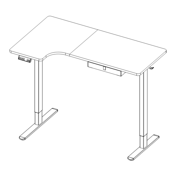
- Page 1 User Manual MI-15002 Please scan this QR code to visit the product page L-Shaped Sit Stand Desk...
- Page 2 Thank you for choosing Mount-It Read the entire instruction manual before you start installation and assembly. If you have any questions regarding any of the instructions or warnings, please contact Mount-It! for assistance. CAUTION: Use with products heavier than the rated weights indicated may result in instability causing possible injury. •...
-
Page 3: Using The Controller
USING THE CONTROLLER Please retain these instructions for future reference Short-press the [S] button, and the display will flash. Press the button to save , ,or the current height setting to that button. Press the button, and the desk will move to the height that was previously set for that button. Press the button, and the desk will move to the height that was previously set for that button. -
Page 4: Package Contents
PACKAGE CONTENTS LONG SIDE PLATE SHORT SIDE PLATE DESKTOP DESKTOP LEGS CROSSBAR CROSSBAR CONNECTOR CROSSBAR CROSSBAR LONG FOOT SHORT FOOT CLOTH DRAWER BRACKETS CLOTH DRAWER CABLE HOLDER TEMPLATE CONTROL PANEL POWER ADAPTER MOTOR CONNECTION CABLE HARDWARE CONTENTS d (x8) a (x32) b (x24) c (x2) M6x10 BOLT... - Page 5 Step 1 Assembling the Leg Sections 1-1 Assemble the Feet Attach the Short Foot (#L) to one Leg (#E), using Bolts (#b) and tighten until secure using the 5mm Hex Wrench (#e). Attach the Long Foot (#K) to the other Leg (#E), using Bolts (#b) and tighten until secure using the 5mm Hex Wrench (#e).
- Page 6 1-3 Assembling the Long Crossbar As shown in magnification bubble1, tighten the Bolts (#d) using 4mm Hex Wrench (#f) As shown in magnification bubble2, attach the Crossbar (#F and #G) to the leg with Long Foot using the Bolts (#b) and tighten until secure using the 5mm Hex Wrench (#e). LONG 1-4 Assembling the Short Crossbar As shown in magnification bubble1, tighten the Bolts (#d) using 4mm Hex Wrench (#f)
- Page 7 Step 2 Assembling the Legs and Crossbar 2-1 Attach the Connector Attach the Connector (#H) to the left and right Crossbars as shown in the image, using Bolts (#b) and tighten until secure using the 5mm Hex Wrench (#e). LONG LONG SHORT Option A: Desk Corner...
- Page 8 2-1 Attach the Connector Attach the Connector (#H) to the left and right Crossbars as shown in the image, using Bolts (#b) and tighten until secure using the 5mm Hex Wrench (#e). LONG LONG Option B: Desk Corner Panel will be on your right 2-2 Attach the Rubber Pad Attach the Rubber Pads (#i) to the top of the Frame in the locations shown here.
- Page 9 Step 3 Assembling the Desktop 3-1 Mark the Locations for the Screws (Control Panel on the Left) Lay the Desktop (#A) piece out in the configuration shown below. Position the Template (#P) on the Desktop and use a pencil to mark all the locations for the screws through the template.
- Page 10 3-1 Mark the Locations for the Screws (Control Panel on the Right) Lay the Desktop (#A) piece out in the configuration shown below. Position the Template (#P) on the Desktop and use a pencil to mark all the locations for the screws through the template. CAUTION: Before marking or installing screws ensure your desk frame has been assembled according to Option A so that the control panel will be on the left-hand side after assembly.
- Page 11 Step 4 Attaching the Frame to the Desktop Turn the leg frames over and carefully place it upside down on the desktop. Align the holes on the frame with the holes on the tabletop. Attach the Desk Frame to the Desktop using Screws (#a). Tighten until secure. Option A: Desk Corner Panel will be on your left Option B: Desk Corner...
-
Page 12: Cable Holder
Step 5 Fold the Cable Holder and Cloth Drawer Brackets Fold the Cable Holder and Cloth Drawer Brackets into the shape shown in the image. Fold with care, do not fold and unfold. If needed use the edge of a table or other solid edge to assist with folding them. Cable Holder Cloth Drawer Brackets... - Page 13 Step 6 Assembling the Cable Holder / Headphone Hook / Controller and Cloth Drawer Brackets Using Screws (#c) attach the Control Panel (#Q) to the locations shown. Using Screws (#a) attach the Headphone Hooks (#j) to the locations shown. Attach the Cloth Drawer Brackets (#M) as shown so that they face each other, then attach the Cable Holder (#O).Ensure the Drawer brackets are installed on the outer set of holes as shown below.
- Page 14 Using Screws (#c) attach the Control Panel (#Q) to the locations shown. Using Screws (#a) attach the Headphone Hooks (#j) to the locations shown. Attach the Cloth Drawer Brackets (#M) as shown so that they face each other, then attach the Cable Holder (#O).Ensure the Drawer brackets are installed on the outer set of holes as shown below.
- Page 15 Step 7 Connect the Power Lines and Attach the Cable Clips Connect the Power Lines Connect the Power Lines as shown in the image. Attach the Cable Clips Attach the Cable Clips (#g) to the underside of the desktop as needed. It is recommended that they be placed approximately in the middle of each length of wire to prevent the cords from hanging too low.
- Page 16 Connect the Power Lines Connect the Power Lines as shown in the image. Attach the Cable Clips Attach the Cable Clips (#g) to the underside of the desktop as needed. It is recommended that they be placed approximately in the middle of each length of wire to prevent the cords from hanging too low. Open the Cable Clip as shown in the magnification bubbles, insert the cord and close the clip again.
- Page 17 Step 8 Insert the Cloth Drawer Insert the Cloth Drawer (#N) into the Brackets (#M)
-
Page 18: Step 9 Connect The Power
Step 9 Connect the Power Flip the desk assembly over and connect the Power Adapter (#R) to a wall outlet. RATED Power Input Speed Motion Noise Load Capability 110V-240V 25 mm/s 220 lbs / 100 kg <55dB... - Page 19 Warnings Do not exceed desk Keep area of vertical weight limit. motion free of obstacles. Keep weight on desk Leave enough slack in balanced for correct cables to allow for full range operation and longer life of vertical motion. of components.
Need help?
Do you have a question about the MI-15002 and is the answer not in the manual?
Questions and answers