
Related Manuals for Mount-It! MI-8033


Summary of Contents for Mount-It! MI-8033
- Page 1 User Manual MI-8033 Please scan this QR code to visit the product page ELECTRIC STANDING DESK BASE WITH SINGLE MOTOR...
- Page 2 Thank you for choosing Mount-It Read the entire instruction manual before you start installation and assembly. If you have any questions regarding any of the instructions or warnings, please contact Mount-It! for assistance. CAUTION: Use with products heavier than the rated weights indicated may result in instability causing possible injury. •...
-
Page 3: Using The Controller
USING THE CONTROLLER Please retain these instructions for future reference Short-press the [M] button, and the display will flash. Press the1,2,or3 button to save the current height setting to that button. Press the button to raise the desk continuously until it reaches the highest position of 46.4" (118cm) or the button is released. -
Page 4: Hardware Contents
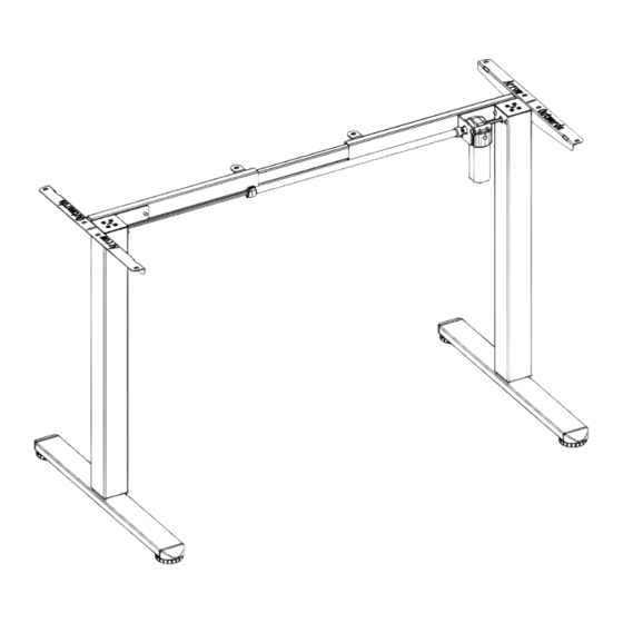
DESKTOP NOT INCLUDED (x1) SUGGESTED DESKTOP SIZE: 40’’X22’’ - 63’’X29.5’’ HARDWARE CONTENTS B (x1) C (x1) D (x1) E (x2) CONNECTOR CROSSBAR CROSSBAR SIDE PLATE F (x1) G (x1) H (x2) I (x1) LEG WITH MOTOR TRANSMISSION ROD FEET J (x1) K (x1) CONTROL PANEL POWER ADAPTER... - Page 5 Step 1 Assembling the Crossbar On a flat and open section of the floor, position the Leg (#F) and Crossbar (#C) in the configuration shown here. As shown in magnification bubble, using the Bolts (#M) tighten until secure using the 5mm Hex Wrench (#Q). Also assemble the Leg with Motor (#G) and Crossbar (#D).
- Page 6 Step 3 Assembling the Feet Attach the Feet (#H) to the Legs (#F &G), using Bolts (#L) and tighten until secure using the 5mm Hex Wrench (#Q). Step 4 Assembling the Connector Insert the Connector (#B) into each end of the Crossbars as shown here.
- Page 7 Step 5 Attaching the Transmission Rod Setting the Desk Legs to the Same Height Before attaching the transmission rod, measure the heights of the right and left desk legs to see if they are set at the same level. If not, the Leg (#F) without the motor will need to be adjusted to match the height of the other Leg with Motor (#G).
- Page 8 Ensure the transmission rod is properly inserted into the hole in the left leg. Extend the rod to connect the other end to the motor drive shaft on the right desk leg. NOTE: Make sure the set screw faces out. Secure the transmission rod to the motor drive shaft by turning the set screw clockwise.
- Page 9 Step 6 Attach the Rubber Pads Attach 10x Rubber Pads (#S) to the top of the frame in the locations shown here. Step 7 Attaching the Frame to the Desktop Turn the leg frame over and carefully place it upside down on the desktop. Adjust the width of the frame and rod until it is suitable for the desktop, then tighten the crossbars (#C, D) to connector (#B) using Bolts (#M) as shown in the magnification bubble, and tighten until secure using the 5mm Hex Wrench (#Q).
- Page 10 Step 8 Assembling the Desktop and Control Panel Attach the Desk Frame to the Desktop using Screws (#N). Tighten until secure. Using Screws (#Q) attach the Control Panel (#J) to the locations shown. Step 9 Connect the Power Lines and Attach the Cable Clips Connect the Power Lines Connect the Power Lines as shown in the image.
- Page 11 Step 10 Connect the Power Flip the desk assembly over and connect the Power Adapter (#K) to a wall outlet. RATED Power Input Speed Motion Noise Load Capability 100V-240V 20 mm/s 154 lbs / 70 kg <55dB...
- Page 12 Warnings Do not exceed desk Keep area of vertical weight limit. motion free of obstacles. Keep weight on desk Leave enough slack in balanced for correct cables to allow for full range operation and longer life of vertical motion. of components.
Need help?
Do you have a question about the MI-8033 and is the answer not in the manual?
Questions and answers