Advertisement
Quick Links
Advertisement

Related Manuals for Mount-It! MI-15003


Summary of Contents for Mount-It! MI-15003
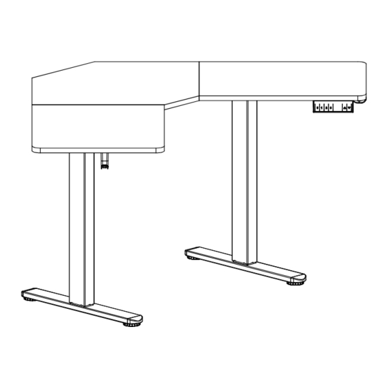
- Page 1 User Manual MI-15003 Please scan this QR code to visit the product page CORNER SIT STAND DESK...
- Page 2 Thank you for choosing Mount-It Read the entire instruction manual before you start installation and assembly. If you have any questions regarding any of the instructions or warnings, please contact Mount-It! for assistance. CAUTION: Use with products heavier than the rated weights indicated may result in instability causing possible injury. •...
-
Page 3: Using The Controller
USING THE CONTROLLER Please retain these instructions for future reference Short-press the [S] button, and the display will flash. Press the button to save , ,or the current height setting to that button. Press the button, and the desk will move to the height that was previously set for that button. Press the button, and the desk will move to the height that was previously set for that button. -
Page 4: Package Contents
PACKAGE CONTENTS A1/A2/A3 DESKTOP LEFT SIDE PLATE RIGHT SIDE PLATE LEFT CROSSBAR RIGHT CROSSBAR LEGS H (x1) I (x1) FEET FRAME JOINT CABLE HOLDER J (x1) K (x1) CONTROL PANEL POWER ADAPTER HARDWARE CONTENTS L (x2) M (x20) N (x40) M3.5x19 SCREW M6x11 BOLT M5x16 SCREW... - Page 5 Step 1 Assembling the Legs and Crossbar On a flat and open section of the floor, position the Legs (#F) and Left and Right Crossbars (#E and #D) in the configuration shown here. As shown in magnification bubble 1, connect the Legs to the Left and Right Crossbars using the Bolts (#M) and tighten until secure using the 5mm Hex Wrench (#O).
- Page 6 Step 3 Attach the Feet Attach the Feet (#G) to the Legs (#F), using Bolts (#M). Step 4 Attach the Rubber Pad Turn the desk over so that it is standing on the feet. Attach the Rubber Pads (#S) to the top of the frame in the locations shown here. All 16 pads will be used.
- Page 7 Step 5 Assemble the Desktop Lay the Desktop (#A) pieces out upside-down in the configuration shown below. Reference the stickers on the underside to identify the proper pieces so that they connect in order left to right A1, A2, A3. Place the Wood Dowels (#P) into the holes on the edge of the desktop pieces and press the boards together over each end of the dowels.
- Page 8 Step 7 Fold the Cable Holder Fold the Cable Holder into the shape shown in the image. Fold with care, do not fold and unfold. If needed use the edge of a table or other solid edge to assist with folding the Cable Holder. Step 8 Attach the Cable Holder Attach the Cable Holder (#I), to the Desktop (#A), using Screws (#N).
- Page 9 Step 9 Attach the Headphone Hook Attach the Headphone Hook (#Q), to the Desktop (#A), using Screws (#N). Step 10 Attach the Control Panel Attach the Control Panel (#J) to the Desktop (#A), using Screws (#L).
- Page 10 Step 11 Connect the Power Lines Firstly, Connect the Power Lines on the Legs (#F) to Control Panel (#J), Secondly, Connect the Power Line on Control Panel (#J) to Power Adapter (#K). Step 12 Attach the Cable Clips Attach the Cable Clips (#R) to the underside of the desktop as needed. It is recommended that they be placed approximately in the middle of each length of wire to prevent the cords from hanging too low.
- Page 11 Step 13 Connect the Power Flip the desk assembly over and connect the Power Adapter (#K) to a wall outlet. RATED Power Input Speed Motion Noise Load Capability 110V-240V 25 mm/s 176 lbs / 80 kg <55dB...
- Page 12 Warnings Do not exceed desk Keep area of vertical weight limit. motion free of obstacles. Keep weight on desk Leave enough slack in balanced for correct cables to allow for full range operation and longer life of vertical motion. of components.
Need help?
Do you have a question about the MI-15003 and is the answer not in the manual?
Questions and answers