
Related Manuals for Mount-It! MI-8034


Summary of Contents for Mount-It! MI-8034
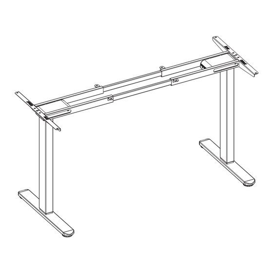
- Page 1 User Manual MI-8034 Please scan this QR code to visit the product page ELECTRIC STANDING DESK BASE WITH DUAL MOTORS...
- Page 2 Thank you for choosing Mount-It Read the entire instruction manual before you start installation and assembly. If you have any questions regarding any of the instructions or warnings, please contact Mount-It! for assistance. CAUTION: Use with products heavier than the rated weights indicated may result in instability causing possible injury. •...
-
Page 3: Using The Controller
USING THE CONTROLLER Please retain these instructions for future reference Short-press the [S] button, and the display will flash. Press the button to save , ,or the current height setting to that button. Press the button, and the desk will move to the height that was previously set for that button. Press the button, and the desk will move to the height that was previously set for that button. -
Page 4: Package Contents
DESKTOP NOT INCLUDED (x1) SUGGESTED DESKTOP SIZE: 40’’X22’’ - 71’’X32’’ PACKAGE CONTENTS B (x2) C (x2) D (x2) CONNECTOR CROSSBAR CROSSBAR E (x2) F (x2) G (x2) SIDE PLATE LEGS FEET H (x1) I (x1) J (x1) CONTROL PANEL POWER ADAPTER EXTENSION LINE HARDWARE CONTENTS K (x28) - Page 5 Step 1 Assembling the Feet Attach one Foot (#G) to one Leg (#F), using Bolts (#K) and tighten until secure using the 5mm Hex Wrench (#N). Repeat this process with the second leg. Step 2 Assembling the Crossbar As shown in magnification bubble, attach the Crossbar (#C and #D) to the leg with Foot using the Bolts (#K) and tighten until secure using the 5mm Hex Wrench (#N).
- Page 6 Step 3 Assembling the Connector Attach the Connector (#B) to the left and right Crossbars as shown in the image, using Bolts (#K) and tighten until secure using the 5mm Hex Wrench (N). Inside...
- Page 7 Step 4 Assembling the Side plates Attach the Side Plate (#E) to the Leg (#F) using Bolts (#K) and tighten until secure using the 5mm Hex Wrench (N). Step 5 Attach the Rubber Pads Attach 12x Rubber Pads (#O) to the top of the frame in the locations shown here.
-
Page 8: Step 7 Attaching The Controller
Step 6 Attaching the Frame to the Desktop Place your desktop upside down on a smooth flat surface. Turn the leg frame over and carefully place it upside down on the desktop. Adjust the width of the frame to suit your desktop by loosening the Bolts (#K) that are securing the Connectors (#B) to the crossbars, then adjust the width as needed and tighten the bolts back down. - Page 9 Step 8 Connect the Power Lines and Attach the Cable Clips Connect the Power Lines Connect the power lines from the legs to the control panel in the locations shown here, using Extension Line (#J) to connect the farther leg depending on whether the control panel is mounted on the left- or right-hand side of the desk.
-
Page 10: Step 9 Connect The Power
Step 9 Connect the Power Flip the desk assembly over and connect the Power Adapter (#I) to a wall outlet. RATED Power Input Speed Motion Noise Load Capability 100V-240V 25 mm/s 220 lbs / 100 kg <50dB... - Page 11 Warnings Do not exceed desk Keep area of vertical weight limit. motion free of obstacles. Keep weight on desk Leave enough slack in balanced for correct cables to allow for full range operation and longer life of vertical motion. of components.
Need help?
Do you have a question about the MI-8034 and is the answer not in the manual?
Questions and answers