VESTEL EVC10 Series Assembly & Installation Manuallines
Electric vehicle charger
Hide thumbs
Also See for EVC10 Series:
- Installation manuallines (152 pages) ,
- User manual (68 pages) ,
- User manual (19 pages)
Table of Contents
Advertisement
Quick Links
Advertisement
Table of Contents

Subscribe to Our Youtube Channel
Related Manuals for VESTEL EVC10 Series


Summary of Contents for VESTEL EVC10 Series
- Page 1 ELECTRIC VEHICLE CHARGER EVC10 Series Installation Guideline...
-
Page 2: Table Of Contents
CONNECT PC TO THE SAME NETWORK WITH SMART BOARD ................36 OPENING WEB CONFIGURATION INTERFACE VIA WI-FI HOTSPOT ..............36 OPENING WEB CONFIGURATION INTERFACE WITH BROWSER .................38 WEB CONFIGURATION INTERFACE ......................39 © 2023 VESTEL - All rights reserved English - 1... -
Page 3: Safety Information
heating sources, may cause reduction of charging SAFETY INFORMATION current or temporary interruption of charging process. • The charging station is intended for outdoor and indoor use. It can also be used in public places. CAUTION • To reduce the risk of fire, electric shock or product RISK OF ELECTRIC damage, do not expose this unit to severe rain, SHOCK... -
Page 4: Ground Connection Warnings
• Defects and damage that occur during • A damaged charging cable can cause fire or give transportation after the delivery of the product you an electric shock. Do not use this product if the to the customer are not covered by the warranty. flexible Charging cable or vehicle cable is frayed, has broken insulation, or shows any other signs •... -
Page 5: Model Description
Blank : Case-B Connection with normal socket T2S : Case-B Connection with shuttered socket T2P : Case-C Connection with Type-2 plug T1P : Case-C Connection with Type-1 plug Cabinet EVC10 © 2023 VESTEL - All rights reserved English - 4... -
Page 6: General Information
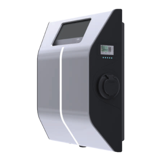
GENERAL INFORMATION INTRODUCTION OF THE PRODUCT COMPONENTS EVC10 Models Information Display RFID Card Reader MID Meter Indicator LED Socket Outlets Illumination LED DIMENSIONAL DRAWINGS © 2023 VESTEL - All rights reserved English - 5... -
Page 7: Technical Specifications
LTE: B1 (2100 MHz), B3 (1800 MHz), B7 (2600 MHz), B8 (900 MHz), B20 (800 MHz) WCDMA: B1 (2100 MHz), B8 (900 MHz) GSM: B3 (1800 MHz), B8 (900 MHz) © 2023 VESTEL - All rights reserved English - 6... -
Page 8: Wireless Lan Transmitter Specifications
2.4 GHz and 5 GHz wireless LANs. Hereby, Vestel Komünikasyon SAN. VE TİC. A.Ş., declares that the radio equipment type EVC is in compliance with Directive 2014/53/EU and Radio Equipment Regulations 2017. The full text of the EU declaration of conformity is available at the following address: doc.vosshub.com. -
Page 9: Authorization
Android / IOS Remote Monitoring & Control Remote Diagnostics Remote Diagnostics over OCPP Load Management Ethernet / Wi-Fi / RS485 / OCPP 1.6 Smart Charging Software Update Via OCPP, Direct Flashing © 2023 VESTEL - All rights reserved English - 8... -
Page 10: Required Equipment, Tools And Accessories
Torx T20-T25 Security Volt Indicator Water Level Screwdriver Flathead Screwdriver Right Angle Screwdriver Adapter (Tip width 2.00-2.5 Pointed Spudger / Torx T20 Security Bit Cat5e or cat6 RJ45 Crimping Tool ethernet cable © 2023 VESTEL - All rights reserved English - 9... -
Page 11: Installing Charging Station
LAN Cable connection Optional Mounting the charging station to the O-Ring pole Mounting the charging station to the Screw M6X20 pole Mounting charging station to wall and Fixing Bracket the pole. © 2023 VESTEL - All rights reserved English - 10... -
Page 12: Product Installation Steps
IP rate of the charger. OPENING AND CLOSING THE FRONT COVER OF THE CHARGING STATION CAUTION RISK OF ELECTRIC SHOCK Please power off the charging station mains supply © 2023 VESTEL - All rights reserved English - 11... - Page 13 Please ensure that the front and back covers are mated properly. Tighten the screws where the hooks of the front cover pass through. Assemble all the screws back in 1.2Nm± 0,1 torque value to finished the assemble of front/back cover. © 2023 VESTEL - All rights reserved English - 12...
-
Page 14: Wall Mount Installation
L-Wrench or Right Angle Screwdriver Adapter using Torx T20 Security Bit with 1.2Nm torque value. Please refer to the next tab to make single phase and three phase wiring connections. © 2023 VESTEL - All rights reserved English - 13... - Page 15 Before closing the cover of the charging station, check next instructions if any function related to these sections are used. © 2023 VESTEL - All rights reserved English - 14...
-
Page 16: Three Phase Charging Station Ac Mains Connection
Press the button on the terminals via a screw driver or a similar tool to be able to insert and remove the cables. Electric Terminal AC Cable Color Earth (Green-Yellow) AC L1 (Brown) AC L2 (Black) AC L3 (Grey) AC Neutral (Blue) © 2023 VESTEL - All rights reserved English - 15... -
Page 17: Data Cable Connection
8 individual wires. in the following order: white/orange, solid orange, white/green, solid blue, white/blue, solid green, white/brown, solid brown. © 2023 VESTEL - All rights reserved English - 16... - Page 18 Termination is complete. Insert the RJ45 connector to the socket as shown in figure below. © 2023 VESTEL - All rights reserved English - 17...
- Page 19 NOTE: Below data connection cables can be inserted through the cable holes; External enable input cable Power optimizer measurement cable Load shedding triggering signal cable Shunt trip module control signal cable for welded relay contact failure © 2023 VESTEL - All rights reserved English - 18...
-
Page 20: Adjusting Current Limiter
32 A 30 A 40 A 32 A 40 A 10 A 10 A 13 A 13 A 16 A 16 A 20 A Phase 25 A 30 A 32 A © 2023 VESTEL - All rights reserved English - 19... -
Page 21: External Enable Input Functionality
If the external relay (RL) is in non-conducting (open), the charging station will not be not be able to charge the electric vehicle. You can connect potential free input signals as shown in above circuitry. Cable Terminal Cable Color 1 (CN2-1) Green 2 (CN2-2) Green + White Green © 2023 VESTEL - All rights reserved English - 20... -
Page 22: Locked Cable Function
Klefr 6924 / 6934, Garo GNM3T / GNM3D, Embedded Power Optimizer with CT, P1 Slimmemeter. If Power Optimizer External Meter is Auto Selected, Power Optimizer value reads from Main board. © 2023 VESTEL - All rights reserved English - 21... - Page 23 To adjust the power optimizer, the slide switch (mode selection switch - SW3) on the control board should be in position to 1 or 2 as shown in figure below. If the switch is set to position 3, power optimizer does not work. Running Power Optimizer © 2023 VESTEL - All rights reserved English - 22...
-
Page 24: Power Optimizer With External Mid Meter
Power Optimizer Meter should be placed just after the main switch of the house as shown in the figure. Power Optimizer Meter wiring connections can be made according to the information below. © 2023 VESTEL - All rights reserved English - 23... - Page 25 10-11: A-B (COM) Modbus connection over RS485 for single phase charging station models. Related board wiring of Power Optimizer connections can be made as shown below: Cable Terminal Description (CN69-2) A (COM) (CN69-1) B (COM) © 2023 VESTEL - All rights reserved English - 24...
-
Page 26: Power Optimizer With External Current Transformer (Ct)
• The slide switch on “ The Embedded Power Optimization Module” should be set as shown in Figure below. (Left side.) NOTE : CAT5 cable length to use should be below 100 meters. Phase 1 Phase 2 Phase 3 CT1 CT2 CT3 © 2023 VESTEL - All rights reserved English - 25... -
Page 27: Mode Selection Switch Settings
The slide switch on the control panel shown in the figure below should be positioned at The wiring of the Linky meter and the control board inside the EV charger must be carried out as shown in the figure below. © 2023 VESTEL - All rights reserved English - 26... - Page 28 You must also connect the I1 and I2 terminals of your Linky meter to the I1 and I2 terminals of the charging station’s communication card. Switch SW2 must be positioned as in the figure below. © 2023 VESTEL - All rights reserved English - 27...
- Page 29 Tariff (Postponed Closed Contact: Off-peak time Supported Charging) Open Contact: Peak time Enable/Disable Charge Point TIC (Dynamic Closed Contact: CP is enabled Not supported Load) Open Contact: CP is disabled © 2023 VESTEL - All rights reserved English - 28...
-
Page 30: Built-In Tic Receiver / Power Optimization Module (Optional)
To use the charging station in TIC and PO mode, the DIP switch on the TIC SR /PO module must be set as shown in the table below. Mode Description Figure Slide Switch Right Position Power optimization by Slide Switch Left Position external CT © 2023 VESTEL - All rights reserved English - 29... -
Page 31: Load Shedding
Cable Terminal Input CN32-1 Load Shedding Input + CN32-2 Load shedding Input – Load Shedding Input State Behaviour Opened Contact Charge with max. available current Closed Contact Charge with 8A © 2023 VESTEL - All rights reserved English - 30... -
Page 32: Monitoring Of Welded Relay Contacts Failure
RCCB (or MCB) at the fuse box of the charging station. The circuitry block diagram that must be used at the fuse box of the charging station is shown below. RCCB SHUNT TRIP CN31 CN58 © 2023 VESTEL - All rights reserved English - 31... -
Page 33: Factory Reset
You must push the button on ACPW board shown in figure below for factory reset. When you hold the button for 5 seconds user configuration will be reset to factory configuration. (e.g OCPP config, Network Config will be back to factory configuration.) © 2023 VESTEL - All rights reserved English - 32... -
Page 34: Setting Ethernet Port Of Charger To Static Ip In Standalone Usage Mode
Note: You can also use factory reset function to set the LAN interface back to DHCP mode again but please well note that all other parameters will be set to factory default parameters. © 2023 VESTEL - All rights reserved English - 33... -
Page 35: Web Configuration Interface Enable / Disable
• If you want to disable the WEB configuration interface, third position of DIP switch should be in “ON“ position as shown in figure below. © 2023 VESTEL - All rights reserved English - 34... -
Page 36: Ocpp Connection
• Installation Settings : Earthing System, Current Limiter Settings, Unbalanced Load Detection, External Enable Input, Lockable Cable, Charging Mode Selection and Power Optimizer Configuration, Location and Load Shedding Minimum Current © 2023 VESTEL - All rights reserved English - 35... -
Page 37: Connect Pc To The Same Network With Smart Board
After connecting to the "Wi-Fi Hotspot" network, the user can open the WEB browser from the computer or mobile device and type the IP address of the charging station, Wi-Fi Hotspot at IP-Address is written on the label. © 2023 VESTEL - All rights reserved English - 36... - Page 38 Interfaces tab. New password character length must be minimum 8 and maximum 63 valid characters a..z A..Z 0..9 .,:;!#^+$%&/ (){[]}=*?-_@<>|. Note: Maximum 3 users can connect to WEB Configuration Interface via Wi-Fi hotspot. It supports 2.4Ghz. © 2023 VESTEL - All rights reserved English - 37...
-
Page 39: Opening Web Configuration Interface With Browser
If you click the “Change Password Button” you will be redirected to the Change Password page. New password must contain at least 1 lowercase letter, 1 uppercase letter, 1 numeric character and minimum 6 characters. © 2023 VESTEL - All rights reserved English - 38... -
Page 40: Web Configuration Interface
Sunrise Time and Sunset Time can be selected when Backlight Level is Display Backlight time based. Settings Backlight level options are Very Low, Low, Mid, High and Time Based. Time values can be between 00:00 and 23:59. © 2023 VESTEL - All rights reserved English - 39... - Page 41 In this part, you can select External Enable Input from Web configuration. Input Options are Disabled or Enabled. In this part, you can select Lockable Cable from Web configuration. Options Lockable Cable are Disabled or Enabled. © 2023 VESTEL - All rights reserved English - 40...
- Page 42 Load Shedding Minimum Current from Web configuration. This parameter can Minimum Current take values between 0 and Current Limiter Value. Current Limiter Value can be set on Current Limiter Settings. © 2023 VESTEL - All rights reserved English - 41...
- Page 43 Select "Autostart" mode to allow charging without the need for authorization. It will be enough to plug to start charging. If you are done with mode selection, click "Save" button. © 2023 VESTEL - All rights reserved English - 42...
- Page 44 You can change the parameters for the slaves from this menu. Number of Connectors, MAC Address, IP Address and Number of Phases are read only parameters, so cannot be changed. © 2023 VESTEL - All rights reserved English - 43...
- Page 45 PASSWORD Page All spaces are mandatory. In FACTORY DEFAULT You can make factory reset to the device. CONFIGURATION Page In LOCAL CHARGE You can view your charging sessions. SESSIONS Page © 2023 VESTEL - All rights reserved English - 44...
Need help?
Do you have a question about the EVC10 Series and is the answer not in the manual?
Questions and answers