
Related Manuals for HMS Networks Intesis IN770MIT00XO040


Summary of Contents for HMS Networks Intesis IN770MIT00XO040
- Page 1 ENGLISH Mitsubishi Electric domestic and commercial with KNX, Serial and IP support IN770MIT00XO040 GATEWAY USER MANUAL Version 1.0.1 Publication date 2023-12-14...
- Page 2 The information in this document shall therefore not be construed as a commitment on the part of HMS Networks and is subject to change without notice. HMS Networks makes no commitment to update or keep current the information in this document.
-
Page 3: Table Of Contents
Mitsubishi Electric domestic and commercial with KNX, Serial and IP support Table of Contents 1. Description and Order Codes ..................... 1 2. Licensing ..........................2 3. General Information ........................ 3 3.1. Intended Use of the User Manual ..................3 3.2. General Safety Information ....................3 3.3. -
Page 4: Description And Order Codes
Description and Order Codes Mitsubishi Electric domestic and commercial with KNX, Serial and IP support 1. Description and Order Codes IN770MIT00xO040 Gateway. Modbus®, KNX®, and Home Automation® gateway for Mitsubishi Electric® air conditioning systems. ORDER CODE LEGACY ORDER CODE IN770MIT00xO040 The x stands for S or M, depending on the license you have purchased. -
Page 5: Licensing
Mitsubishi Electric domestic and commercial with KNX, Serial and IP Licensing support 2. Licensing Distribution license(s) for the IN770MIT00xO040 gateway: Order Code License Maximum groups IN770MIT00SO040 Small IN770MIT00MO040 Medium NOTE The order code may vary depending on the product seller and the buyer's location. Page 2 of 35 USER MANUAL Version 1.0.1... -
Page 6: General Information
General Information Mitsubishi Electric domestic and commercial with KNX, Serial and IP support 3. General Information 3.1. Intended Use of the User Manual This manual contains the main features of this Intesis gateway and the instructions for its appropriate installation, configuration, and operation. The contents of this manual should be brought to the attention of any person who installs, configures, or operates this gateway or any associated equipment. - Page 7 Mitsubishi Electric domestic and commercial with KNX, Serial and IP Admonition Messages and Symbols support IMPORTANT Instruction that must be followed to avoid a risk of reduced functionality and/or damage to the equipment or to avoid a network security risk. NOTE Additional information which may facilitate installation and/or operation.
-
Page 8: Overview
Overview Mitsubishi Electric domestic and commercial with KNX, Serial and IP support 4. Overview This IN770MIT00xO040 gateway supports three applications. Gateway's client interface ↔ Gateway's server interface Modbus TCP and RTU Mitsubishi Electric City Multi systems KNX TP Home Automation IMPORTANT This document assumes that the user is familiar with these technologies. -
Page 9: Inside The Package
Figure 3. Integration of Mitsubishi Electric AC systems into Home Automation installations 4.1. Inside the Package Items included: • Intesis IN770MIT00xO040 Gateway • USB Mini-B type to USB Type-A cable • Installation Sheet 4.2. Main Features • Several applications available: Configurable for Modbus TCP and RTU, KNX, and Home Automation communication protocols. -
Page 10: Gateway General Functionality
10). 4.3. Gateway General Functionality With this Intesis IN770MIT00xO040 gateway, you can easily integrate Mitsubishi Electric City Multi systems into an installation based on Modbus TCP, Modbus RTU, KNX, or Home Automation. To do so, the gateway acts as a server device of the installation itself, accessing all signals from each air conditioner unit and controlling the whole AC network. -
Page 11: Hardware
This integration requires the Mitsubishi Electric City Multi AC system to be equipped with a Mitsubishi Electric Centralized Controller for M-Net. This Centralized Controller offers the signals of the City Multi AC system through XML protocol to its Ethernet port, which is accessed by the Intesis IN770MIT00xO040 gateway. IMPORTANT... - Page 12 Mounting Mitsubishi Electric domestic and commercial with KNX, Serial and IP support Wall mounting Press the top side mobile clips in the rear panel until you hear a click. Use the clip holes to fix the gateway on the wall using screws. NOTE Use M3 screws, 25 mm (1") length.
-
Page 13: Connection
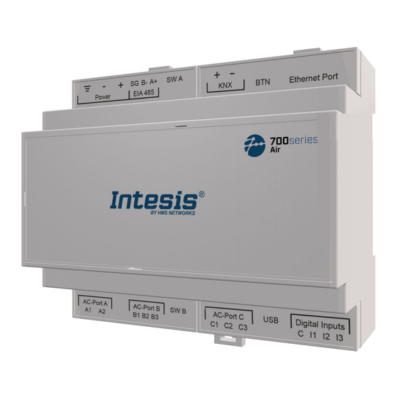
Mitsubishi Electric domestic and commercial with KNX, Serial and IP Connection support 5.3. Connection CAUTION Disconnect all systems from power before manipulating and connecting them to the gateway. IMPORTANT Keep communication cables away from power and ground wires. 5.3.1. Gateway Connectors Figure 4. - Page 14 Connection Mitsubishi Electric domestic and commercial with KNX, Serial and IP support Connectors' wiring: IMPORTANT For all connectors, use solid or stranded wires (twisted or with ferrule). Cross-section/gauge per terminal: • One core: 0.2 .. 2.5 mm / 24 .. 11 AWG •...
-
Page 15: Connection Procedure For The Ac Unit
Mitsubishi Electric domestic and commercial with KNX, Serial and IP Connection support IMPORTANT • Use SELV-rated NEC class 2 or limited power source (LPS) power supply. • Respect the polarity. • Connect the gateway's ground terminal to the installation grounding. •... -
Page 16: Connection Procedure For Knx
Connection Mitsubishi Electric domestic and commercial with KNX, Serial and IP support For Modbus RTU: Connect the Modbus RTU communication cable to the gateway's EIA-485 port. The connector for the EIA-485 bus is a green pluggable terminal block labeled SG (signal ground), B-, and A+. IMPORTANT Observe polarity. -
Page 17: Connection To A Pc For Configuration
Mitsubishi Electric domestic and commercial with KNX, Serial and IP Connection support • Connecting directly to a Home Automation device: use a crossover Ethernet UTP/FTP CAT5 or higher cable. • Connecting to a hub or switch of the LAN of the building: use a straight Ethernet UTP/FTP CAT5 or higher cable. -
Page 18: Gateway Layout
Gateway Layout Mitsubishi Electric domestic and commercial with KNX, Serial and IP support 5.4. Gateway Layout Figure 5. Disposition of hardware elements in the gateway Plastic covers numbered in the image as ①, ②, ③, and ④ can be easily disassembled. The following sections explain each element in more detail: LEDs, DIP switches, and the push button. -
Page 19: Led Indicators
Mitsubishi Electric domestic and commercial with KNX, Serial and IP LED Indicators support 5.5. LED Indicators Table 1. LEDs location and behavior Cover Color Description Top side LED 1 (PWR) Green Power on (not programmable) LED 2 (ERR) Blinking: Hardware error Under frontal cover ①... -
Page 20: Push Button
Push Button Mitsubishi Electric domestic and commercial with KNX, Serial and IP support 5.7. Push Button Find the push button at the top side, between the KNX and the Ethernet connectors (see the figure Disposition of hardware elements in the gateway (page 15)). -
Page 21: Technical Specifications
Mitsubishi Electric domestic and commercial with KNX, Serial and IP Technical Specifications support 5.8. Technical Specifications Plastic, type PC (UL 94 V-0). Color: Light Grey. RAL 7035 Housing Net dimensions (dxwxh): Millimeters: 90 x 106 x 58 mm / Inches: 3.5 x 4.2 x 2.3" Wall: Use M3 25 mm (1") length screws. -
Page 22: Dimensions
Dimensions Mitsubishi Electric domestic and commercial with KNX, Serial and IP support 5.9. Dimensions • Net dimensions (DxWxH) Millimeters: 90 x 106 x 58 mm Inches: 3.5 x 4.2 x 2.3" IMPORTANT Leave enough clear space to wire the gateway easily and for the subsequent manipulation of elements such as connectors, DIP switches, etc. -
Page 23: Available Applications
Mitsubishi Electric domestic and commercial with KNX, Serial and IP Available Applications support 6. Available Applications 6.1. Integration into Modbus Systems 6.1.1. Modbus Registers NOTICE This part is common for Modbus RTU and TCP. Functions to read Modbus registers: • 03 Read Holding Registers. •... - Page 24 Integration into Modbus Systems Mitsubishi Electric domestic and commercial with KNX, Serial and IP support Register name Possible values Modbus address formula Fan Speed (all the IC groups) 1: Set Fan Speed Mid-1 ((CTRL#-1)*30)+15 Fan Speed (all the IC groups) 1: Set Fan Speed Mid-2 ((CTRL#-1)*30)+16 Fan Speed (all the IC groups)
- Page 25 Mitsubishi Electric domestic and commercial with KNX, Serial and IP Integration into Modbus Systems support Register name Possible values Modbus address formula 0: Auto 1: Horizontal 2: Position 2 Vane position 3: Position 3 (((CTRL#-1)*50)+Group#*100)+3 R, W 4: Position 4 5: Vertical 6: Swing Cool or dry: 19 ..
- Page 26 Integration into Modbus Systems Mitsubishi Electric domestic and commercial with KNX, Serial and IP support Register name Possible values Modbus address formula Celsius: 4.5 .. 35°C Cool/dry/auto(upper) dual temperature setpoint (x10°C) (((CTRL#-1)*50)+Group#*100)+27 R, W Fahrenheit: 40 .. 95°F Celsius: 4.5 .. 90°C Heating ATW &...
-
Page 27: Integration Into Knx Systems
Mitsubishi Electric domestic and commercial with KNX, Serial and IP Integration into KNX Systems support 6.2. Integration into KNX Systems 6.2.1. KNX signals IMPORTANT The signals available depend on the gateway configuration and/or the unit type (AC indoor unit, Air-to-water booster unit, heat pump, etc.) Table 4. - Page 28 Integration into KNX Systems Mitsubishi Electric domestic and commercial with KNX, Serial and IP support Description Object function Flags 1: Horizontal 2: Position-2 Vane position (all the groups) 3: Position-3 DPT_Enumerated (1byte) 4: Position-4 5: Vertical 1: Set auto vane Vane position AUTO (all the groups) DPT_Switch (1bit) 0: Stop auto vane...
- Page 29 Mitsubishi Electric domestic and commercial with KNX, Serial and IP Integration into KNX Systems support Description Object function Flags 0: Cool 1: Dry 2: Fan Status_Operation mode IC DPT_Enumerated (1byte) R, T 3: Heat, 4: Auto 5: Setback 0: Cool Control_Mode Cool/Heat IC DPT_Heat/Cool (1bit) 1: Heat...
- Page 30 Integration into KNX Systems Mitsubishi Electric domestic and commercial with KNX, Serial and IP support Description Object function Flags 1: Heat recovery mode active Status_Heat recovery mode LOSSNAY DPT_Switch (1bit) R, T 0: Heat recovery mode not active Control_Bypass mode LOSSNAY 1: Set bypass mode DPT_Switch (1bit) 1: Bypass mode active...
- Page 31 Mitsubishi Electric domestic and commercial with KNX, Serial and IP Integration into KNX Systems support Description Object function Flags Thersholds: 0 .. 37 % Control_Fan Speed scaling (4stages) 38 .. 62 % DPT_Scaling (1byte) 63 .. 87 % 88 .. 100 % Thersholds: 25 % Status_Fan Speed scaling (4stages)
- Page 32 Integration into KNX Systems Mitsubishi Electric domestic and commercial with KNX, Serial and IP support Description Object function Flags Thersholds: 0 .. 30 % 31 .. 50 % Control_Vane position scaling DPT_Scaling (1byte) 51 .. 70 % 71 .. 90 % 91 ..
- Page 33 Mitsubishi Electric domestic and commercial with KNX, Serial and IP Integration into KNX Systems support Description Object function Flags 0: Off Status_Operational Status for Lossnay or OA 1: Low DPT_Enumerated (1byte) R, T 2: High 0: Enabled Control_On/Off control disablement DPT_Enable (1bit) 1: Disabled 0: Enabled...
- Page 34 Integration into KNX Systems Mitsubishi Electric domestic and commercial with KNX, Serial and IP support Description Object function Flags Celsius: 4.5 .. 90°C Status_Heating ECO ATW temperature setpoint DPT_Value_Temp (2byte) R, T Fahrenheit: 40 .. 194°F Celsius: 4.5 .. 90°C Control_Auto single temperature setpoint DPT_Value_Temp (2byte) Fahrenheit: 40 ..
-
Page 35: Integration Into Home Automation Systems
Mitsubishi Electric domestic and commercial with KNX, Serial and IP Integration into Home Automation Systems support 6.3. Integration into Home Automation Systems 6.3.1. Home Automation Signals The following tables list all available Home Automation signals for this gateway. NOTE • SET: Command used to control the indoor unit. It is sent by the client. •... -
Page 36: Late Configuration: Change The Gateway's Protocol
Late Configuration: Change the Gateway's Protocol Mitsubishi Electric domestic and commercial with KNX, Serial and IP support 7. Late Configuration: Change the Gateway's Protocol Reconfiguring the gateway with a different protocol is very easy: Connect the gateway to the PC and open the configuration tool Intesis MAPS. Select the new template you need. -
Page 37: Error Codes
Mitsubishi Electric domestic and commercial with KNX, Serial and IP Error Codes support 8. Error Codes NOTE These error codes are the same for all applications. Error Code Description 65535 (-1) Communication error between the gateway and the AC unit No active error 1102 Discharge temperature high... - Page 38 Error Codes Mitsubishi Electric domestic and commercial with KNX, Serial and IP support 6608 M-NET transmission error 6608 M-NET without response 6831 Remote controller transmission error (reception error) 6832 Remote controller transmission error (transmission error) 6840 Transmission error with the indoor/outdoor unit (reception error) 6841 Transmission error with the indoor/outdoor unit (transmission error) Error in the inter-connection cable in the indoor/outdoor unit, indoor unit number...
Need help?
Do you have a question about the Intesis IN770MIT00XO040 and is the answer not in the manual?
Questions and answers