Advertisement
Quick Links
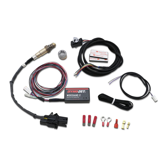
Wideband 2
Installation Guide
PARTS LIST
1
WIDEBAND 2
1
DATA ACQUISITION CABLE
1
OXYGEN SENSOR
1
OXYGEN SENSOR CABLE
1
WELD BUNG, PLUG, AND WASHER
2
PORT SEALS
3
WIRE TAPS
1
BLADE FUSE TAP
PLEASE READ ALL DIRECTIONS BEFORE STARTING INSTALLATION
1
MINI BLADE FUSE TAP
1
QUICK LUG
1
TERMINAL STRIP PLUG
2
VELCRO
1
ALCOHOL SWAB
3
ZIP TIES
2
DYNOJET DECALS
98200017.04
Advertisement

Related Manuals for Dynojet Wideband 2


Summary of Contents for Dynojet Wideband 2
- Page 1 Wideband 2 Installation Guide PARTS LIST WIDEBAND 2 MINI BLADE FUSE TAP DATA ACQUISITION CABLE QUICK LUG OXYGEN SENSOR TERMINAL STRIP PLUG OXYGEN SENSOR CABLE VELCRO WELD BUNG, PLUG, AND WASHER ALCOHOL SWAB PORT SEALS ZIP TIES WIRE TAPS DYNOJET DECALS...
- Page 2 - Narrow B and O 2 O ut grey - Analog Input (0-5v) black/white - Digital G round red - 12v black - G round C AN C AN LE D Function B utton 2 WIDEBAND 2 INSTALLATION GUIDE 98200017...
- Page 3 M18 x 1.5mm weld boss on the exhaust system. On vehicles equipped with catalytic converters, Dynojet recommends installing the weld boss before the converters. Vehicles that do not utilize catalytic converters are free to install the boss anywhere in the exhaust, but we recommend keeping it within thirty inches of the exhaust port.
- Page 4 The sensor may become damaged if the vehicle is running and the Wideband 2 is not receiving power. In the event that you do not have power running to the sensor, remove the sensor and install the weld boss plug included in the Wideband 2 kit.
- Page 5 M18 x 1.5mm weld boss on the exhaust system. On vehicles equipped with catalytic converters, Dynojet recommends installing the weld boss before the converters. Vehicles that do not utilize catalytic converters are free to install the boss anywhere in the exhaust, but we recommend keeping it within thirty inches of the exhaust port.
- Page 6 The sensor may become damaged if the vehicle is running and the Wideband 2 is not receiving power. In the event that you do not have power running to the sensor, remove the sensor and install the weld boss plug included in the Wideband 2 kit.
- Page 7 INSTALLING THE WIDEBAND 2-MOTORCYCLE On most motorcycle applications the best place to mount the Wideband 2 module is under the seat or in the tail section of the motorcycle. Verify the CAN-Link Ports are accessible for data transfer. Note: Install the CAN-Link Expansion Port seals when the ports are not in use.
- Page 8 Connect the black and the black/white wires to a good ground location with the eyelets provided. When using the Analog Input on the Wideband 2, you may need to run the black/white wire to the sensor ground. For example, using the Analog Input to measure TPS voltage, you would tie the black/white wire to the TPS sensor ground.
- Page 9 The wires blue pierce a foam gasket. Install the supplied terminal strip plug when mounting the Wideband 2 under the hood or in an area that may be exposed to moisture or dirt. trim terminal strip plug Note: The supplied terminal strip plug may need to be trimmed before installation.
- Page 10 Refer to the data acquisition documentation for more information. SIMULATED NARROW BAND OUTPUT WIRE The Wideband 2 provides a Simulated Narrow Band Output white/blue - R PM grey - Analog Input signal.
- Page 11 A 2 1/16th diameter hole is required for the gauge which can be mounted in-dash or in an aftermarket gauge pod. The gauge cable must be routed to the Wideband 2 Module and connected to the four pin connector or to the optional Data Acquisition/Gauge Cable (P/N 76950118).
- Page 12 If no other ground exists, you must run a ground wire from the data acquisition system to the vehicle chassis ground. Refer to the data acquisition documentation for more information. 12 WIDEBAND 2 INSTALLATION GUIDE 98200017...
- Page 13 SENSOR CONDITION TEST The Wideband 2 has a built in circuit which allows you to test the sensor accuracy and condition. 8000 7000 Verify the sensor is exposed to clean ambient air. 6000 5000 Verify the Wideband 2 has been on for at least one sensor ok minute.
- Page 14 Use the following instructions to set up your gauge. Dipswitch 1—Input Voltage Dipswitch 1 is used to set the input voltage for the Wideband 2 or Wideband Commander. • When using the WB2, set dipswitch 1 to the ON position. • When using the Wideband Commander, set dipswitch 1 towards the number 1 (down).
- Page 15 Dipswitch 1—Input Voltage Dipswitch 1 is used to set the input voltage for the Wideband 2 or Wideband Commander. • When using the Wideband 2, set dipswitch 1 to the ON position. • When using the Wideband Commander, set dipswitch 1 towards the number 1 (down).
- Page 16 TRUTH TRUTH IN IN PERFORMANCE PERFORMANCE 800-992-4993 - DYNOJET.COM © 2008-2024 DYNOJET RESEARCH ALL RIGHTS RESERVED...
Need help?
Do you have a question about the Wideband 2 and is the answer not in the manual?
Questions and answers