
Related Manuals for System Q NiteDevil 2020 PTZ960


Summary of Contents for System Q NiteDevil 2020 PTZ960
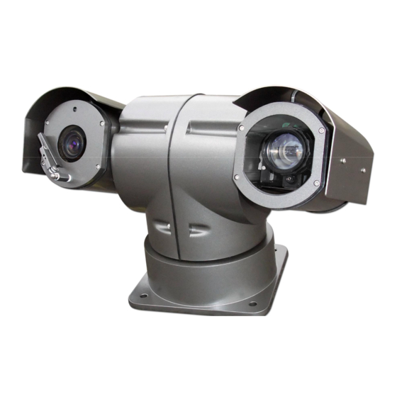
- Page 1 Robo NiteDevil 2020 + IR Installation and Operation Manual PTZ960 HIGH Speed Armoured Pan Tilt Zoom 24V AC model with Infrared Camera & Wiper Models Covered PTZ960N 30x Zoom Version 1.0 Last Revised: 31/07/2012...
-
Page 2: Table Of Contents
CONTENTS TABLE Description Page No. Contents Safety Precautions Key Functions Special Dome Features – 4 channel alarm input activation & channel alarm output Getting the PTZ up & running Overview – introduction to fitting PTZ equipment RS485 Wiring methods & Tips Overcoming RS485 data loss using an RS485 distributor Setting up the PTZ Camera RS485 connection –... -
Page 3: Safety Precautions
Please read this operation manual carefully before installing and using this unit !!!! Please read the following; 1. Please read the operation manual carefully before installing and operating the product. 2. The PTZ960 requires a 24v AC 2.5A power supply. The rated input voltage of the camera in the PTZ is 12V!!!! This gets its power from the PTZ960 and does not require a separate PSU. -
Page 4: Key Functions
KEY FUNCTIONS The Armoured PTZ960 – Description of Functions This intelligent armoured PTZ is a hi-tech CCTV product, which incorporates a high-clarity colour camera. It has a panoramic variable speed PAN/TILT movement, a multifunctional decoder, a character generator and an on-board processor for logic handling. The PTZ960 is easy to connect, install, maintain and operate, and has many special features. -
Page 5: Special Dome Features - 4 Channel Alarm Input Activation & Channel Alarm Output
b. If you have an N camera module you will notice that there are different keyboard commands used. Extended commands are available by setting the MORE option in the Advanced menu so that for example a tour can be initiated using a CALL 65. A full list is detailed and options detailed in the MAIN MENU instructions. -
Page 6: Getting The Ptz Up & Running
Heater Control The PTZ960 incorporates a heater to clear condensation. The option is found under DEFOGGER in the Control Setup menu. Getting the PTZ up and running! You MUST connect up the PTZ and your control equipment on a workbench or kitchen table before the actual site installation and CHECK YOU KNOW HOW TO INSTALL IT CORRECTLY!!!!!!!!!!!!!!!!!. - Page 7 Equipment Cable Needed 1. Data signal CAT5 cable Keypad or You can also send the video signal back along a second pair in a CAT5 cable using baluns. Note you cannot send 24v AC power down CAT5. 2. Video signal RG59 or similar You can combine both the video and power into one cable if you...
-
Page 8: Rs485 Wiring Methods & Tips
CAT 5 CCT CAMERA 24 V AC CAT5 Carries Video & LOCAL Control Data 240V --- Video & Power RG59+2 Video & Power BALUN TRADITIONAL CAT5 Carrying Data CAMERA 240V JUNCTION BOX Free Lead Supplied CO-AX RG59 KEYPAD MONITOR Many installation companies can get the power and video signal correct, but struggle with the control of the PTZ using the keypad or DVR using the RS485 data. - Page 9 PLEASE NOTE - Using inferior cables, or installing the PTZ in an environment with strong electromagnetic interference, or connecting a lot of PTZ domes to the same cable carrying the RS485 signal will reduce the maximum transmitting distance. 3. RS485 Connection methods METHOD 1 –...
- Page 10 ..Main controller Daisy-Chain connection WITH SHORT SPURS for the RS485 PTZ control signal (one main radial with very short spurs to each PTZ off it, keeping the spurs to less than 10 meters) TIP - The connection of a 120 termination resistor: The JP1 termination resistor is ready fitted on the PTZ pcb, all you have to do to set it, is to move the jumper from Pins 2 &3 to pins 1 &...
-
Page 11: Overcoming Rs485 Data Loss Using An Rs485 Distributor
As the star configuration is not in conformity with the requirements of RS485 standards, problems such as signal reflections may arise, especially when there are long cable connections. The results are that control signals are decreased and the PTZ may not respond to, or just responds intermittently to the controller. If your STAR circuit is not too extensive with PTZ 1 each spur in the region of 20-50 metres you can... - Page 12 spurs, each spur can have up to 4 PTZs. This means that you could theoretically have up to 4 individual spurs of over 1000 metres each to control up to 16 PTZs in total. Ideally you would put just one PTZ on each spur from the PTZ750 but up to 4 PTZs are generally acceptable. The following diagram shows a typical use of the PTZ750 RS485 distributor.
-
Page 13: Setting Up The Ptz Camera
Setting up the PTZ Camera 1. Connection of the System There are many ways to wire up a PTZ system. If you have read the introduction at the beginning of these instructions you should have got a good idea what your options are. -
Page 14: Rs485 Connection - Connecting The Keypad Or Dvr To The Ptz960
Powering the PTZs- All the PTZs will need power. For this PTZ it is a 24V A.C power supply. The power supply must be capable of delivering at least 2.5A per PTZ. You can either power each PTZ with its own PSU locally to it or have the PSU’s remotely situated perhaps near the keyboard or DVR. - Page 15 The PTZ960 range adopts the following RS485 convention: ORANGE = RS485 + or A YELLOW = RS485 – or B You should initially be wiring the dome to the keyboard or DVR on your workshop bench or at least your kitchen table to prove you know how to get everything to work.
-
Page 16: Connecting The Video Out Of The Ptz
Connecting the video out of the PTZ The PTZ960 has a short BNC lead attached to it, this is the lead that carries the video signal from the built-in camera. You need to extend this lead to the “VIDEO-IN” of the DVR or monitor. Use a good quality RG59 coax cable or similar to do this. - Page 17 24V AC INPUT RS485 RS485 - ‘B’ YELLOW + ‘A’ ORANGE RS485 COMBINER RS485 Data Cable RS485 INPUT ON DVR 24 VAC Last Revised: 31/07/2012...
-
Page 18: If You Are Using More Than One Ptz On A Site
SW2 sets up the protocol. This switch is dealt with later in these instructions. For most System Q equipment they should always be set to PELCO-D 2400 baud rate. In the diagram this is correct. The Jumper on the far right either enables or disables the 120 resistor. -
Page 19: Setup Of The Protocol And The Default Baud Rate
As shown in Table 2, SW2 is used to set the protocol and the baud rate used by the PTZ camera. DIP-1 to DIP-4 of SW2 is used to select protocols and a maximum of 16 different protocols can be selected. Pelco-D 2400 is used for most System Q equipment. DIP-5 and DIP-6 are for the baud rate. - Page 20 Some protocols and the setting of the dipswitches on normal baud rates for these protocols are shown as follows: NEON/ 9600Bps PANASO NI C/ 9600Bps PELCO - D/ 2400Bps KALATEL/ 4800Bps PELCO - P/ 4800Bps ALEC/ 9600Bps PELCO - P/ 9600Bps Ul t r ak/ 9600Bps Setup of the Baud Rate.
-
Page 21: Using The Ptz730 Keypad With The Ptz960
Using the PTZ730 keypad with the PTZ960 NOTE 1: For more detailed instructions in setting up the keypad or using one of our other keypads, please refer to the instruction manual supplied with the product. NOTE 2: The PTZ730 keypad requires you to press the function key first followed by the value e.g <CAM>... -
Page 22: Presets And Other Functions
PRESETS and other functions. The PTZ960 has up to 128 presets that once programmed will stay in the PTZ’s non-volatile memory so they will be retained even after a power cut. What is a preset? A preset is a particular area or object that the PTZ was looking at and has been stored into its memory so when the preset is “called-up”... -
Page 23: Patrols (Tours) - How To Set Them Up And Use Them
Patrols (Tours) – How to set them up and use them A patrol (tour) is simply a collection of at least three preset camera locations that are run in sequence with the PTZ stopping at each location for a brief period of time and then moving on to the next preset. For example, you could use a patrol so that an outside PTZ camera points at a gate, then at a side doorway, then zooms out to get an overall shot of a car park and finally zooming in on a delivery bay, before repeating the whole cycle again. - Page 24 Setting the Patrol (Tour) To setup the patrol/tour you need to enter the Advanced Menu System by selecting <CALL> 95 <Enter>on the keypad or <CALL> 64 <Enter>. (Call varies according to module type). You will see the Main Menu displayed on the screen. Enter the password to enter the menu.
-
Page 25: Auto Scan - How To Set It Up - Calling The Auto Scan
Now exit the menu by moving the Joystick down, selecting EXIT and then moving the Joystick to the right to return to the Main Menu. Again use the Joystick to select EXIT and exit the Advanced Menu System by selecting the right pan movement. Calling the Patrol (Tour) There are two methods of initiating the patrol or tour. - Page 26 Enter the password to enter the menu. The Default password is 111111. See Advance Setup menu to change. You will see the Main Menu displayed on the screen. Using the joystick up/down direction movement, select the MOTION SETUP menu. Use the joystick pan right movement to enter this menu. In the AUTO SCAN menu select the scan number (maximum 3), then the speed.
-
Page 27: Record Pattern- What Is A Record Pattern
RECORD PATTERN- What is a record pattern This dome has an option to store a record pattern. A record pattern consists of a continuous sequence of standard pan and tilt movements or lens commands recorded for at least a 120 second interval. -
Page 28: How To Set It Up - Running The Record Pattern
You will see the Main Menu displayed on the screen. Using the joystick up/down direction movement, select the MOTION SETUP menu. Use the joystick pan right movement to enter this menu. STEP 1 - In the PATTERNS menu select PATTERN NUMBER and enter number from 1 ~3 . Now select RECORD PATTERN. -
Page 29: Schedule - What Is It? - How To Set It Up - Special Tips
SCHEDULE - What is it? The schedule allows you to set an Autoscan, Tour or Pattern from a specified date and time to a specified date and time on a day or days of the week. SCHEDULE - How to set it up The schedule requires the Time to be set first in the Advance menu. - Page 30 2. How to set Schedule SCHEDULE SCHEDULE Allows a schedule to be selected for SCH ID: controlling what the PTZ is required to do. ENABLED Ensure Time is set in Advanced menu first. REPEAT See 1 above. ACTION 1 PATROL <TIME>...
- Page 31 SAVE After making changes to the schedule you must save them or they will not be applied. Note that if the date range is incorrect then it will not be able to save the schedule. The user will be informed with a prompt in the bottom left side of the display screen. CLEAR This clears the schedule.
-
Page 32: Using The Advanced Menu System
USING THE DOME’S ADVANCED FUNCTIONS- On Screen Graphics (OSD) – The PTZ960 series boasts six patrol (tour) options, three auto scan options and three record pattern options. All these can be configured using the OSD. <CALL> 64 <Enter> To bring up the camera menu press <CALL> 95 <Enter> or (varies with module type) . -
Page 33: The Menu System
THE MENU SYSTEM Using the Menu System. This menu system allows the user to alter the dome menu instruction options and settings using a control keypad. This first page shows the initial main menu page and only describes the general functions. The following pages show the main menu option selected on the left hand side of the page and a breakdown of that menu page on the right hand side of the page. -
Page 34: System Setup
To access System Setup press the OPEN button on keypad or move the Joystick to the right. The menu below will be displayed. MAIN MENU SYSTEM SETUP SYSTEM SETUP DISPLAY SETUP SYSTEM INFORMATION AUTO FLIP CAMERA SETUP PROP PAN SPD MOTION SETUP PRIVACY MASK LOW POWER... -
Page 35: Display Setup
Move the Joystick down to select Display Setup and press the OPEN button or move the Joystick to right. The menu below will be displayed. MAIN MENU DISPLAY SETUP SYSTEM SETUP DISPLAY SETUP <CAMERA ID> <see 1 below> CAMERA SETUP <ANGLE DISPLAY>... -
Page 36: Camera Setup
Move the Joystick down to select Camera Setup and press the OPEN button or move the Joystick to right. The menu below will be displayed. MAIN MENU CAMERA SETUP D-ZOOM SYSTEM SETUP DISPLAY DISPLAY SETUP FOCUS MODE AF AUTO CAMERA SETUP AUTO MOTION SETUP PRIVACY MASK... - Page 37 screen. (Only Sony cameras have this function.) <WB/AE SETUP> WB/AE SETUP White Balance Mode/Automatic Exposure. AE MODE AUTO SHUTTER WB MODE AUTO R GAIN B GAIN WDR MODE ON / OFF <EXPCOMP SETUP> RETURN AE MODE MANUAL / AUTO / SHUTTER Normally set to AUTO.
-
Page 38: Motion Setup
Move the Joystick down to select Motion Setup and press the OPEN button or move the Joystick to the right. The menu below will be displayed. MAIN MENU MOTION SETUP <PRESETS> (1) SYSTEM SETUP <AUTOSCAN> (2) DISPLAY SETUP <PATROLS> (3) CAMERA SETUP <PATTERNS>... - Page 39 SET START LIMIT To set the start position enter this menu item and then move the joystick to position the camera at the starting position and then press CLOSE to save the start position. SET END LIMIT To set the end position select this menu item and then move the joystick to position the camera at the end position and then press CLOSE to save the end position.
- Page 40 RUN PATROL Click on this menu item and then press CLOSE to start patrol. CLEAR PATROL Click to clear a patrol. RETURN Returns to MOTION SETUP menu. <PATTERNS> (4) PATTERNS Allows recording of a pattern for up to 120 seconds. Up to 3 patterns can be recorded.
- Page 41 <TIME> SCHEDULE TIME START DATE 00 – 00 – 00 END DATE 00 – 00 – 00 START DATE 00 – 00 – 00 This identifies the day, month or year START TIME 00 – 00 – 00 according to the format set in Advance END DATE 00 –...
-
Page 42: Privacy Mask
<CLEAR> (6) CLEAR This option clears all options. CLEAR ALL PRELABEL CLEAR ALL PRELABEL Clears all presets. CLEAR ALL SCAN CLEAR ALL PATROLS CLEAR ALL SCAN Clears all scans. CLEAR ALL PATTERNS RETURN CLEAR ALL PATROLS Clears all patrols. CLEAR ALL PATTERNS Clears all patterns. - Page 43 Main Menu displayed and use the PTZ down direction key to move down to Privacy Masking and press right direction key to enter. Select Privacy Mask area number from 01 – 08, select shade (Black, White or Grey), switch display on and enter EDIT MASK using down and right arrow direction keys.
-
Page 44: Advance Setup - Includes Wiper And Demister Functions
ADVANCE SETUP MAIN MENU SYSTEM SETUP <HOME SETUP> DISPLAY SETUP <PASSWORD> CAMERA SETUP <CAM ID SETUP> MOTION SETUP <FAN CONTROL> PRIVACY MASK <TIME SET> <AUX CONTROL ADVANCE SETUP SYSTEM RESET <MORE> RETURN EXIT <HOME SETUP> (1) HOME SETUP This option must not be confused with the Alarm function that can be set with different AUTO HOME timing settings. - Page 45 ADVANCE SETUP MAIN MENU SYSTEM SETUP <HOME SETUP> DISPLAY SETUP <PASSWORD> CAMERA SETUP <CAM ID SETUP> MOTION SETUP <FAN CONTROL> PRIVACY MASK <TIME SET> ADVANCE SETUP <AUX CONTROL SYSTEM RESET <MORE> EXIT RETURN PASSWORD (2) PASSWORD This option allows password protection. PASSWORD MODIFY KEY * * * * * *...
- Page 46 ADVANCE SETUP MAIN MENU SYSTEM SETUP <HOME SETUP> DISPLAY SETUP <PASSWORD> CAMERA SETUP <CAM ID SETUP> MOTION SETUP <FAN CONTROL> PRIVACY MASK <TIME SET> <AUX CONTROL ADVANCE SETUP SYSTEM RESET <MORE> EXIT RETURN CAM ID SETUP (3) CAM ID SETUP This enters the software ID settings menu CAMERA S/N: 0001...
- Page 47 ADVANCE SETUP MAIN MENU SYSTEM SETUP <HOME SETUP> DISPLAY SETUP <PASSWORD> CAMERA SETUP <CAM ID SETUP> MOTION SETUP <FAN CONTROL> PRIVACY MASK <TIME SET> ADVANCE SETUP <AUX CONTROL SYSTEM RESET <MORE> EXIT RETURN FAN CONTROL (4) To set the fan control menu settings. FAN CONTROL SWITCH SWITCH FAN...
- Page 48 ADVANCE SETUP MAIN MENU SYSTEM SETUP <HOME SETUP> DISPLAY SETUP <PASSWORD> CAMERA SETUP <CAM ID SETUP> MOTION SETUP <FAN CONTROL> PRIVACY MASK <TIME SET> ADVANCE SETUP <AUX CONTROL SYSTEM RESET <MORE> EXIT RETURN TIME SET TIME SET This is the time setting menu and is used by the DATE FORMAT: YYMMDD SCHEDULE in the MOTION SETUP menu.
- Page 49 ADVANCE SETUP MAIN MENU SYSTEM SETUP <HOME SETUP> DISPLAY SETUP <PASSWORD> CAMERA SETUP <CAM ID SETUP> MOTION SETUP <FAN CONTROL> PRIVACY MASK <TIME SET> ADVANCE SETUP <AUX CONTROL> SYSTEM RESET <MORE> EXIT RETURN WIPER ON / OFF AUX CONTROL This sets Wiper option ON or OFF WIPER: WIPER MODE: 1 TIMES...
-
Page 50: System Reset - Exit
ADVANCE SETUP2 LANGUAGE (1) Set English or Chinese LANGUAGE: ENGLISH (1) SET NORTH: SET NORTH (2) SHORTCUT: OFF / ON Set direction for calculating Privacy Mask PAN SPEED SHORTCUT (3) RETURN Set ON if you have the SONY N camera module. This option allows the user to start a Tour, Autoscan or Pattern using a keyboard or DVR with PTZ control. - Page 51 Using the N camera module If the N module camera is used, there are different preset functions available. Note that you must have the Shortcut option set to ON in the Advanced menu for all call functions to work. CALL 1 CALL TWICE FOR MENU Reserved CALL 64...
-
Page 52: Camera Module Commands - Controlling One Camera Then Another
Controlling one camera then another. If you look at the image of the LCD display you can see the CAM=001 indicates that the keyboard is ready to talk to camera with address 1. In the dome the address 1 is set as default in the factory. You need to alter the DIP-switches within the domes to address 2, 3 etc if you have multiple domes on the same site, refer to the previous instructions how to set the DIP Switches. -
Page 53: Installation Instructions
Installation Instructions Product Dimensions Installation Steps 1. Remove the bottom plate of the pan/tilt. 2. In accordance with the instructions detailed earlier in this manual set the address, protocol, baud rate and termination jumper. 3. Install the bottom plate of the pan/tilt and ensure that the waterproof seal is carefully located ensuring a good seal. - Page 54 5. Board Mount Using the anti-shock device use it as a template for drilling mounting holes through the support. You will need to provide necessary bolts to hold the device securely. Now fit the anti-shock device top plate to the base of the PTZ with the four M8 bolts using one elastic gasket and one flat gasket on each bolt as per diagram below.
- Page 55 7. Cable Connections There are two cable sockets, one 7 pin and one 10 pin. The 7 pin is for power, video and RS485 connection and the 10 pin for alarm connection. Note that the 24vAC PTZ960 has alarm connections but the 12vDC PTZ950 has no alarm connections.
-
Page 56: Channel Alarm Input Activation & Single Channel Alarm Output
4 channel alarm input activation & single channel alarm output One of the special features of this PTZ is that it has four in-built alarm channels to call four independent presets. This means that for example you may have a door contact and when the contact is closed, it sends a 0 volt alarm switch to the PTZ on one of the four alarm channels. - Page 57 Each of the four alarm channels call a different dedicated preset number when the 0v switch is detected by the PTZ. This allows the PTZ to move immediately to the selected preset position in an alarm condition. The following example shows how a preset can be triggered: when Alarm Channel No 1 is activated it calls preset number 29 when Alarm Channel No 2 is activated it calls preset number 30 when Alarm Channel No 3 is activated it calls preset number 31...
- Page 58 Al ar m i nput ALM - 4 ALM - 1 ALM - 2 ALM - 3 Al ar m out put EXAMPLE: ALARM 1 CONNECTED TO VOLTAGE FREE DOOR CONTACT Last Revised: 31/07/2012...
- Page 59 13) Connecting the Output Alarm In addition to the alarm inputs, the PTZ960 will activate an alarm output if an alarm input is triggered. There are two connections for the alarm output, a common and either a normally open or a normally closed connection. Again this is a 0 volt switch and could be used for example to close a circuit to an audible alarm, lighting or other warning devices.
-
Page 60: Vi. Technical Data Table
VI. Technical data table Sony N module Resolution 580TVL Optical Zoom In-Phase System In-Phase Inside Video Output 1.0 Vp-p/75 White Balance Auto / Manual Power Supply AC 24V±10% 2.5A Specifications Power Consumption 50 VA Weight 7.5Kg Operating Temperature -35ºC ~ 55ºC Waterproof Class IP66 Installation... -
Page 61: Appendix A: Lightning Proof And Surge Signal Proof
Appendix A: Lightning Proof and Surge Signal Proof This product adopts TVS lightning proof technology to prevent damage by a lightning strike below 1500 W and surge impulse signals. However it is also necessary to ensure that the following precautions are taken to ensure electrical safety: Keep the communication cables at least 50 meters away from high voltage equipment or cables.
Need help?
Do you have a question about the NiteDevil 2020 PTZ960 and is the answer not in the manual?
Questions and answers