
Related Manuals for System Q PTZ800


Summary of Contents for System Q PTZ800
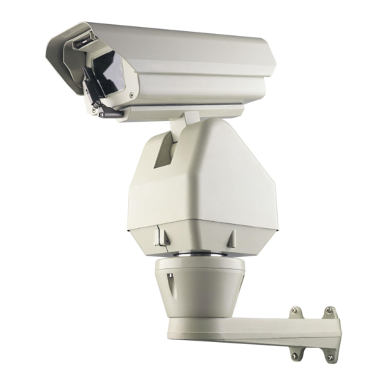
- Page 1 Traditional PTZ range Installation and Operation Manual Outdoor HIGH Speed Traditional Pan Tilt Zoom 24V AC model with IR Day-Night Module Models Covered PTZ800 PTZ827 Version 1.0...
-
Page 2: Table Of Contents
Page No. Contents Safety Precautions Key Functions Special PTZ800 Features – 2 channel alarm input activation Getting the dome up & running Overview – introduction to fitting PTZ equipment RS485 Wiring methods & Tips The connection of a 120 ohm termination resistor... -
Page 3: Safety Precautions
Please read this operation manual carefully before installing and using this unit !!!! Please read the following; 1. Please read the operation manual carefully before installing and operating the product. 2. The actual dome requires a 24v AC power supply. The rated input voltage of the camera is 12V!!!! This gets its power from the dome and does not require a separate PSU. -
Page 4: Key Functions
KEY FUNCTIONS Description of Functions This intelligent traditional PTZ is a hi-tech CCTV product, which incorporates a high-clarity colour camera. It has a panoramic variable speed PAN/TILT movement, a multifunctional decoder, a character generator and an on-board processor for logic handling. The PTZ is easy to connect, install, maintain and operate, and has many features. -
Page 5: Special Ptz800 Features - 2 Channel Alarm Input Activation
4. Special PTZ800 Features Weatherproof This PTZ is IP66 weatherproof rated. Control Features Automatic temperature control feature and manual control for rain wiper and defroster. 2 channel alarm input activation One of the special features of this PTZ is that it has two in-built alarm channels to call two independent presets. -
Page 6: Overview- Introduction To Fitting Ptz Equipment
Overview- introduction to fitting PTZ equipment Generally speaking, PTZ cameras requires four things; 1- They require a power supply and a cable to supply this power to the dome. Often, external PTZs are 24V A.C but some mini pan and tilt domes are 12V. 2- They require a cable to get the video signal back to the monitor or recording device. - Page 7 The control signal (RS485) is nearly always sent along a “ twisted-pair” type cable. The twists in the cable help prevent interference affecting the data signal by “ shielding” it. Many installation companies use a CAT5 type or similar cable to run out to the PTZs to carry the data signal. If you are considering using baluns please note - DVR’...
-
Page 8: Rs485 Wiring Methods & Tips
RS485 Wiring methods & Tips >>>>> 1. Characteristics of RS485 As specified by RS485 standards, RS485 is a half-duplex data transmission type with characteristic impedance of 120 . The maximum load capacity is 32 units (PTZs, keyboards and DVRs). 2. Transmission distances of RS485 Signals using CAT5 or similar cables Selecting a CAT5 or similar sized twisted pair data transmission cable, the maximum theoretical transmitting distances are as follows: Baud Rate... -
Page 9: The Connection Of A 120 Ohm Termination Resistor
..Standard Daisy-Chain connection for the RS485 PTZ control signal (just the last PTZ only has the 120 resistor set to on, the first device is the keyboard and has the 120 built in as default) This next diagram is a slight variation on the Daisy Chain arrangement. -
Page 10: Overcoming Rs485 Data Loss Using An Rs485 Distributor
STAR method of connection. In some circumstances you may need to adopt a star configuration for practical purposes. For instance, all the PTZs may be so scattered on a large site that running out separate spurs to each dome in a “ STAR” array is the only practical solution. - Page 11 Where you wish to run several separate CAT5 cables out to send the RS485 data signal out to the PTZs you are in effect correcting the STAR method of RS485 data distribution. As previously mentioned the problem with the Star method is that it is not actually designed for RS485 but generally works okay if you follow the previous notes on getting the 120ohm resistor setting right, as per the previous notes.
-
Page 12: Setting Up The Traditional Ptz Camera
Setting up the Traditional PTZ Camera 1. Connection of the System There are many ways to wire up a PTZ system. If you have read the introduction at the beginning of these instructions you should have got a good idea what your options are. -
Page 13: Rs485 Connection - Connecting The Keypad Or Dvr To The Ptz
The following table gives you an indication of the maximum lengths that you can achieve using this cable the composite cable and the PTZ800 range PTZs. Power cable requirement – Assuming a starting voltage of 24V A.C is applied at the PSU end. - Page 14 The PTZ730 and PTZ700 are two keypads that can be used PTZ730 keypad with the PTZ800 series. On the rear of the keypads you will see the RS485 connections. Ensure they are connected correctly i.e the RS485 + A line and the RS485 – B line.
-
Page 15: Connecting The Video Out Of The Ptz
If you use cores from two different pairs in the CAT5 cable you will not get the benefit of the shielding effect of the cable twists and the PTZ will function erratically. You must always use a core from a PAIR, not two cores from two different pairs!! Connecting the video out of the PTZ The PTZ has a short BNC lead attached to it, this is the lead that carries the video signal from the... - Page 16 24V AC INPUT RS485 RS485 - ‘ B’ + ‘ A’ RS485 INPUT ON...
-
Page 17: If You Are Using More Than One Dome On A Site
If you’ re using more than one PTZ on a site Each PTZ has a unique “ address” so that if you are using more than one on a site the keyboard “ talks” to the right PTZ when you want it to pan, tilt or zoom. If you only have the one PTZ on the site then the default “... -
Page 18: Setup Of The Protocol And The Default Baud Rate
As shown in Table 2, SW2 is used to set the protocol of communication and the baud rate used by the dome camera. DIP-4 to DIP-1 of SW2 is used to select protocols and a maximum of 16 different protocols can be selected. Pelco-D 2400 is used for most System Q equipment. DIP status... - Page 19 Some protocols and the states of the coding switches of normal baud rates of these protocols are shown as follows: NEON/ 9600Bps PANASONI C/ 9600Bps PELCO - D/ 2400Bps KALATEL/ 4800Bps PELCO - P/ 4800Bps ALEC/ 9600Bps PELCO - P/ 9600Bps Ul t r ak/ 9600Bps Special Note: The SW2 dipswitch settings for the above example protocols may be inverted.
-
Page 20: Using The Ptz730 Keypad With The Traditional Ptz Series
Using the PTZ730 keypad with the Traditional PTZ series NOTE 1: For more detailed instructions in setting up the keypad or using one of our other keypads, please refer to the instruction manual supplied with the product. NOTE 2: The PTZ730 keypad requires you to press the function key first followed by the value e.g <CAM>... -
Page 21: Presets And Other Functions
PRESETS and other functions. The PTZ has up to 128 presets that once programmed with stay in the PTZ’ s non-volatile memory so they will be retained even after a power cut. What is a preset? A preset is a particular area or object that the PTZe was looking at and has been stored into its memory so when the preset is “... -
Page 22: Patrols (Tours) - How To Set Them Up And Use Them
Patrols (Tours) – How to set them up and use them A patrol (tour) is simply a collection of at least three preset camera locations that are run in sequence with the PTZ stopping at each location for a brief period of time and then moving on to the next preset. For example, you could use a patrol so that an outside PTZ camera points at a gate, then at a side doorway, then zooms out to get an overall shot of a car park and finally zooming in on a delivery bay, before repeating the whole cycle again. - Page 23 Setting the Patrol (Tour) To setup the patrol/tour you need to enter the Advanced Menu System by selecting <CALL> 95 <Enter>on the keypad. You will see the Main Menu displayed on the screen. The main menu can also be opened by calling preset 1 twice within 4 seconds. Using the joystick up/down direction movement, select the PROGRAM menu.
- Page 24 Now exit the menu by moving the Joystick down, selecting EXIT and then moving the Joystick to the right to return to the Main Menu. Again use the Joystick to select EXIT and exit the Advanced Menu System by selecting the right pan movement. Calling the Patrol (Tour) There are two methods of initiating the patrol or tour.
-
Page 25: Auto Scan - How To Set It Up - Calling The Auto Scan
AUTO SCAN- How to set it up Auto-scan scans between two points. These are not presets as per the patrol(tour) facility but auto scan selection points. You may program only one auto scan. STEP 1 – Select the required camera by pressing the <CAM> button and then entering <camera address>... -
Page 26: Record Pattern- What Is A Record Pattern
RECORD PATTERN- What is a record pattern This PTZ has an option to store a record pattern. A record pattern consists of a continuous sequence of standard pan and tilt movements or lens commands recorded within a 40 second interval. A record pattern does not use presets. - Page 27 You will see the Main Menu displayed on the screen. Using the joystick up/down direction movement, select the PROGRAM menu. Use the joystick pan right movement to enter this menu. In the PROGRAM menu select RECORD PATTERN followed by pressing CLOSE button to save.
-
Page 28: Using The Ptz800' S Advanced Functions
USING THE PTZ800 ADVANCED FUNCTIONS- On Screen Graphics (OSD) – The PTZ800 series boasts six patrol (tour) options, an auto scan option and a record pattern option. All these can be configured using the OSD. To bring up the camera menu press <CALL> 95 <Enter>. -
Page 29: Using The Advanced Menu System
THE ADVANCED MENU SYSTEM Using the Advanced Menu System. This menu system allows the user to alter the PTZ menu instruction options and settings using a control keypad. This first page shows the initial main menu page and only describes the general functions. The following pages show the main menu option selected on the left hand side of the page and a breakdown of that menu page on the right hand side of the page. -
Page 30: Display Setup
DISPLAY SETUP To access Display Setup press the OPEN button on keypad or move the Joystick to the right. The menu below will be displayed. MAIN MENU DISPLAY SETUP 1. DISPLAY SETUP ID DISPLAY 2. CAMERA SETUP ID POS TOP-L 3. - Page 31 CAM DISPLAY ON / OFF When this is set to ON the camera screen will be opened. To toggle the settings move the Joystick to the right or press the OPEN button. To return to Main Menu use the Joystick down movement to RETURN and press the OPEN button on the keypad or move the Joystick to the right.
-
Page 32: Camera Setup
CAMERA SETUP Move the Joystick down to select Camera Setup and press the OPEN button or move the Joystick to the right. The menu below will be displayed. CAMERA SETUP MAIN MENU 1. DISPLAY SETUP SLOWSHUTTER AUTO 2. CAMERA SETUP BACK LIGHT 3. - Page 33 D-ZOOM ON / OFF Setup of digital zooming. This allows the digital zoom function to be switched on or off. To toggle the settings move the Joystick to the right or press the OPEN button. To return to Main Menu use the Joystick down movement to RETURN and press the OPEN button on the keypad or move the Joystick to the right.
-
Page 34: Control Setup
CONTROL SETUP Move the Joystick down to select Control Setup and press the OPEN button or move the Joystick to the right. The menu below will be displayed: MAIN MENU CONTROL SETUP 1. DISPLAY SETUP WIPER 2. CAMERA SETUP DEFROSTER 3. - Page 35 HOME OPTION enter HOME OPTION sub menu To enter this option move the Joystick to the right. The HOME OPTION submenu on the right will be displayed. AUTO HOME ON / OFF HOME POS 01 / PATROL n DWELL TIME 06 MIN AUTO HOME ON / OFF...
-
Page 36: Program
PROGRAM Move the Joystick down to select Program and press the OPEN button or move the Joystick to the right. The menu below will be displayed. PROGRAM MAIN MENU AUTO PAN START POS 1. DISPLAY SETUP AUTO PAN END POS 2. - Page 37 0-9, A-Z, +, - and space. NOTE: The first character of the title must be 0-9 or A-Z. SET PATROL To edit data for a patrol/tour. Select sequence number of patrol by using the Joystick pan left or pan right, press OPEN button to select edit mode and edit using the up/down Joystick movement, setting the POS (preset number), the Joystick pan right to select the dome speed (SP) and the dwell time (TM) followed by the CLOSE button to save and exit.
-
Page 38: Cam Default Set
CAM DEFAULT SET No sub-menu option for this. MAIN MENU 1. DISPLAY SETUP 2. CAMERA SETUP 3. CONTROL SETUP 4. PROGRAM 5. CAM DEFAULT SET 6. DOME RESET 7. EXIT CAM DEFAULT SET This option sets the camera default settings. Press the CLOSE button to exit or move down using the up and down toggle to move to the EXIT point. -
Page 39: Reset Pt
RESET PT MAIN MENU 1. DISPLAY SETUP 2. CAMERA SETUP 3. CONTROL SETUP 4. PROGRAM 5. CAM DEFAULT SET 6. RESET PT 7. EXIT RESET PT This option resets the PT titles. The following display will be output OPERATION WILL Use the Joystick left or right pan to toggle between YES CLEAR ALL TITLES and NO. -
Page 40: Exit
EXIT MAIN MENU 1. DISPLAY SETUP 2. CAMERA SETUP 3. CONTROL SETUP 4. PROGRAM 5. CAM DEFAULT SET 6. RESET PT 7. EXIT Use the Joystick to select the option and press the CLOSE button to exit menu. Controlling one camera then another. If you look at the image of the LCD display you can see the CAM=001 indicates that the keyboard is ready to talk to camera with address 1. -
Page 41: Special Presets
Special Presets Presets 51 to 60 are used for special functions. Therefore presets 51 to 60 must not be used for patrols, alarm linkages or patrol points otherwise error conflicts will arise. Preset Set Preset Call Preset Wiper ON Wiper OFF Defroster ON Defroster OFF Auxiliary Output 24vAC ON... -
Page 42: Physical Installation Of The Ptz800
Physical installation of the PTZ800 Technical Elevations... -
Page 43: Wall Mounting
Wall Mounting The PTZ can be fitted using the wall bracket or the base plate. If fitting using wall bracket, first secure the wall bracket using M8 screws. There is a removable plate under the support arm. See diagrams below. This plate can be removed so that connecting cables can be fitted. -
Page 44: Base Plate Mounting
Connecting cables for wall mounting Base Plate Mounting Use the base mounting plate as a template for drilling holes into fixing position. The next step is to fit the base plate to the bottom of the PTZ using M6 x 20 screws. - Page 45 The third step is to fit the PTZ and base plate to the fixing position. Ensure that the connecting wires are placed into the groove under the mounting plate to avoid them being damaged. The diagram opposite show the PTZ fitted.
-
Page 46: Wiring Connections - Alarm Connections
Wiring connections Input of AC Power Supply BLACK Input of AC Power Supply YELLOW Control Wire RS485- B ORANGE Control Wire RS485+ A VIDEO OUT Video Output Alarm connections Green Yellow Blue Alarm Input 1 Yellow Alarm Input 2 Green, Blue Alarm Common Terminal The alarm input must be a zero volt switch otherwise internal circuits could be damaged. -
Page 47: Channel Alarm Input Activation
2 channel alarm input activation One of the special features of this dome is that it has two in-built alarm channels to call two independent presets. This means that for example you may have a door contact and when the contact is closed, it sends a 0 volt alarm switch to the PTZ on one of the two alarm channels. -
Page 48: Technical Data Table
the building. The requirement is to ensure that during out of hours the entrance door is not breached and if the door is opened the PTZ will automatically switch to preset point 3. The PTZ alarm 1 channel is connected to a door contact on the main entrance door using a CAT5 twisted pair. -
Page 49: Appendix A: General Information - Troubleshooting
Appendix A: General Information Troubleshooting To avoid problems and to ensure the PTZ has been correctly setup it is always advisable to test the equipment in your workshop before you go on-site. If workshop setup is successful, any problems experienced on-site will be greatly minimised.
Need help?
Do you have a question about the PTZ800 and is the answer not in the manual?
Questions and answers