
Related Manuals for SCHUNK AFS3 138 PMI


Summary of Contents for SCHUNK AFS3 138 PMI
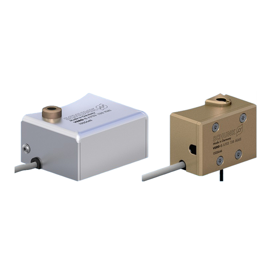
- Page 1 VERO-S Monitoring System AFS3 138 PMI, AFS3 138 MMS Assembly and Operating Manual Translation of Original Operating Manual...
- Page 2 Your SCHUNK team Customer Management Tel. +49-7572-7614-1300 Fax +49-7572-7614-1039 cmm@de.schunk.com Please read the operating manual in full and keep it close to the product. 06.00 | AFS3 138 PMI, AFS3 138 MMS | VERO-S Monitoring System | en | 1372107...
-
Page 3: Table Of Contents
7.2 Connecting the AFS3 138 MMS ..............21 7.3 Programming the switching positions for the clamping slide monitoring with the AFS3 138 MMS ................22 06.00 | AFS3 138 PMI, AFS3 138 MMS | VERO-S Monitoring System | en | 1372107... - Page 4 11.2 AFS3 138 MMS..................28 12 Sensor for presence monitoring of the clamping pallet ........29 12.1 Assembly, connection, technical data proximity switch IN60......30 06.00 | AFS3 138 PMI, AFS3 138 MMS | VERO-S Monitoring System | en | 1372107...
-
Page 5: General
1.1.3 Sizes This operating manual applies to the following sizes: Monitoring system for quick-change pallet system AFS3 138 PMI AFS3 138 MMS 06.00 | AFS3 138 PMI, AFS3 138 MMS | VERO-S Monitoring System | en | 1372107... -
Page 6: Warranty
(see catalog or data sheets when ordering separately) Teaching device ID 9988354 suitable for AFS3 PMI Teaching device + power supply ID 40103327 suitable for AFS3 PMI 06.00 | AFS3 138 PMI, AFS3 138 MMS | VERO-S Monitoring System | en | 1372107... -
Page 7: Basic Safety Notes
Make sure that the product is used only in the context of its defined application parameters, } 3 [/ 11]. Only use high-quality cooling emulsions with anti-corrosive additives during processing. 06.00 | AFS3 138 PMI, AFS3 138 MMS | VERO-S Monitoring System | en | 1372107... -
Page 8: Personnel Qualification
Personal protective equipment serves to protect staff in the event of a danger that may interfere with their health or safety at work. Observe the valid safety and accident prevention regulations. 06.00 | AFS3 138 PMI, AFS3 138 MMS | VERO-S Monitoring System | en | 1372107... -
Page 9: Notes On Safe Operation
Follow local regulations on dispatching product components for recycling or proper disposal. 06.00 | AFS3 138 PMI, AFS3 138 MMS | VERO-S Monitoring System | en | 1372107... -
Page 10: Fundamental Dangers
Stand clear of suspended loads and do not step into their swiveling range. Never move loads without supervision. Do not leave suspended loads unattended. 06.00 | AFS3 138 PMI, AFS3 138 MMS | VERO-S Monitoring System | en | 1372107... -
Page 11: Technical Data
Operating temperature + 5°C to + 60°C Required level of cleanliness IP 30 in accordance with DIN EN 60529 06.00 | AFS3 138 PMI, AFS3 138 MMS | VERO-S Monitoring System | en | 1372107... -
Page 12: Function
The inductive proximity switch must be positioned for a reliable function at a flush installation height to the cover plug of the protective cover. 06.00 | AFS3 138 PMI, AFS3 138 MMS | VERO-S Monitoring System | en | 1372107... -
Page 13: Afs3 138 Mms
For reliable functionality, the inductive proximity switch must be positioned at a flush installation height in the installation housing. 06.00 | AFS3 138 PMI, AFS3 138 MMS | VERO-S Monitoring System | en | 1372107... -
Page 14: General Installation Notes
NSE3 138-V1 NSE3 138-V1-K NSE3 138-V4 NSE3 138-V4-K NSE3 138-P NSE3 138-P-K NSE-T3 138 NSE-T3 138-K NSE-T3 138-V1 NSE-T3 138-V1-K NSE-T3 138-V4 NSE-T3 138-V4-K 06.00 | AFS3 138 PMI, AFS3 138 MMS | VERO-S Monitoring System | en | 1372107... -
Page 15: Mounting / Connection / Programming Of The Afs3 138 Pmi
1. Select installation side on the quick-change pallet system. 2. Unscrew M5 grub screw on clamping slide (if present). 3. Unscrew fastening screws of the protective cover, remove protective cover vertically. 06.00 | AFS3 138 PMI, AFS3 138 MMS | VERO-S Monitoring System | en | 1372107... -
Page 16: Connecting The Afs3 138 Pmi
Via an interface, two switching outputs "S1 + S2" are provided to the user for clamping condition monitoring. "Open" clamping module "Clamped" clamping module "Clamped without clamping pins" clamping module 06.00 | AFS3 138 PMI, AFS3 138 MMS | VERO-S Monitoring System | en | 1372107... -
Page 17: Programming The Switching Positions For The Clamping Slide Monitoring With The Afs3 138 Pmi
The teach-in process must be completed in 410 seconds, otherwise the positions will not be transferred and stored in the inductive position measuring system. 06.00 | AFS3 138 PMI, AFS3 138 MMS | VERO-S Monitoring System | en | 1372107... - Page 18 Programming is generally only possible in the first 6 minutes after switching on the sensor. The programming is then blocked. To re-enable programming, the sensor must be disconnected briefly from the power supply. 06.00 | AFS3 138 PMI, AFS3 138 MMS | VERO-S Monitoring System | en | 1372107...
-
Page 19: Mounting / Connection / Programming Of The Afs3 138 Mms
4. Unscrew fastening screws of the lid onto the AFS3 138 MMS, remove lid. 5. Remove seals and lay to one side. 06.00 | AFS3 138 PMI, AFS3 138 MMS | VERO-S Monitoring System | en | 1372107... - Page 20 17. Insert seals in the housing and in the lid, screw on lid. 18. Monitoring system AFS3 138 MMS is operational 06.00 | AFS3 138 PMI, AFS3 138 MMS | VERO-S Monitoring System | en | 1372107...
-
Page 21: Connecting The Afs3 138 Mms
This magnetic field can be generated by: – Crane loading with a magnet – Magnetic chucks – Other magnetic sources in the immediate proximity 06.00 | AFS3 138 PMI, AFS3 138 MMS | VERO-S Monitoring System | en | 1372107... -
Page 22: Programming The Switching Positions For The Clamping Slide Monitoring With The Afs3 138 Mms
LED (A1) on the teaching device or the yellow LED on the sensor flashes and then goes out. 06.00 | AFS3 138 PMI, AFS3 138 MMS | VERO-S Monitoring System | en | 1372107... -
Page 23: Function Test On The Clamping Module With Connected, Ready For Operation Afs3 138 Mms
(A1: 0; A2: 1) While the monitoring system is operating, the corresponding clamping stroke positions of the clamping module have to detect the required switching signal. 06.00 | AFS3 138 PMI, AFS3 138 MMS | VERO-S Monitoring System | en | 1372107... -
Page 24: Maintenance And Care
The system may only be commissioned again once the faults have been removed. For example, by replacing the damaged unit. 06.00 | AFS3 138 PMI, AFS3 138 MMS | VERO-S Monitoring System | en | 1372107... -
Page 25: Troubleshooting
Cable plug-in connection to the Check plug connections, if necessary tighten. Proximity supply cable switch type IN or replace specially available feed cable if required. 06.00 | AFS3 138 PMI, AFS3 138 MMS | VERO-S Monitoring System | en | 1372107... -
Page 26: The Afs3 138 Mms Is Not Working
Cable plug-in connection to the Check plug connections, if necessary tighten. Proximity supply cable switch type IN or replace specially available feed cable if required. 06.00 | AFS3 138 PMI, AFS3 138 MMS | VERO-S Monitoring System | en | 1372107... -
Page 27: Parts Lists
Inductive proximity switches O-ring Ø 42 x 1.5 O-ring Ø 3 x 1 O-ring Ø 8 x 1 Cylindrical screw Cylindrical screw Countersunk screw Set-screw Grommets 06.00 | AFS3 138 PMI, AFS3 138 MMS | VERO-S Monitoring System | en | 1372107... -
Page 28: Assembly Drawings
Assembly Drawings 11 Assembly Drawings 11.1 AFS3 138 PMI 11.2 AFS3 138 MMS Insertion for sensor MMS PI2 from any of 3 sides 06.00 | AFS3 138 PMI, AFS3 138 MMS | VERO-S Monitoring System | en | 1372107... -
Page 29: Sensor For Presence Monitoring Of The Clamping Pallet
Check that the cable is correctly connected and installed. There must be sufficient distance between the switches and sources of interference and their supply cables. 06.00 | AFS3 138 PMI, AFS3 138 MMS | VERO-S Monitoring System | en | 1372107... -
Page 30: Assembly, Connection, Technical Data Proximity Switch In60
Cable diameter [mm] min. bending radius (dynamically) [mm] min. bending radius (statically) 17.5 [mm] Number of cores Length of the connection cable [mm] Connecting plug 06.00 | AFS3 138 PMI, AFS3 138 MMS | VERO-S Monitoring System | en | 1372107... - Page 31 06.00 | AFS3 138 PMI, AFS3 138 MMS | VERO-S Monitoring System | en | 1372107...
- Page 32 H.-D. SCHUNK GmbH & Co. Spanntechnik KG Lothringer Str. 23 D-88512 Mengen Tel. +49-7572-7614-0 info@de.schunk.com schunk.com Folgen Sie uns I Follow us Wir drucken nachhaltig I We print sustainable...
Need help?
Do you have a question about the AFS3 138 PMI and is the answer not in the manual?
Questions and answers