SCHUNK VERO-S Assembly And Operating Manual
Monitoring system
Hide thumbs
Also See for VERO-S:
- Assembly and operating manual (27 pages) ,
- Assembly and operating manual (74 pages)

Subscribe to Our Youtube Channel
Related Manuals for SCHUNK VERO-S


Summary of Contents for SCHUNK VERO-S
- Page 1 Translation of the assembly and operating manual VERO-S Monitoring system AFS3 138 PMI, AFS3 138 MMS Assembly and Operating Manual Superior Clamping and Gripping...
- Page 2 Imprint Copyright: This manual is protected by copyright. The author is SCHUNK GmbH & Co. KG. All rights reserved. Any reproduction, processing, distribution (making available to third parties), translation or other usage - even excerpts - of the manual is especially prohibited and requires our written approval.
-
Page 3: Table Of Contents
Table of contents Table of contents 1 General ........................5 1.1 About this manual ....................5 1.1.1 Presentation of Warning Labels ..............5 1.1.2 Applicable documents ................... 5 1.1.3 Sizes ....................... 5 1.2 Warranty ........................6 1.3 Scope of delivery ...................... 6 1.4 Accessories ....................... - Page 4 Table of contents 7.2 Connecting the AFS3 138 MMS ................24 7.3 Programming the switching positions for the clamping slide monitoring with the AFS3 138 MMS ....................... 26 7.4 Signal statuses after teach-in process for the AFS3 138 MMS ......27 7.5 Function test on the clamping module with connected, ready for operation AFS3 138 MMS ........................
-
Page 5: General
Applicable documents • General terms of business* • Catalog data sheet of the purchased product * • Assembly and Operating Manual VERO-S clamping system * The documents marked with an asterisk (*) can be downloaded on our homepage schunk.com 1.1.3... -
Page 6: Warranty
General Warranty If the product is used as intended, the warranty is valid for 24 months from the date of delivery from the production facility under the following conditions: • Observe the applicable documents, ( 1.1.2, Page 5) • Observe the ambient conditions and operating conditions, (... -
Page 7: Basic Safety Notes
Spare parts Use of unauthorized spare parts Using unauthorized spare parts can endanger personnel and damage the product or cause it to malfunction. • Use only original spare parts or spares authorized by SCHUNK. 01.00|1372106_AFS3 138 PMI_AFS3 138 MMS |en... -
Page 8: Environmental And Operating Conditions
Basic safety notes Environmental and operating conditions Required ambient conditions and operating conditions Incorrect ambient and operating conditions can make the product unsafe, leading to the risk of serious injuries, considerable material damage and/or a significant reduction to the product's life span. •... -
Page 9: Personal Protective Equipment
Basic safety notes Personal protective equipment Use of personal protective equipment Personal protective equipment serves to protect staff in the event of a danger that may interfere with their health or safety at work. • Observe the valid safety and accident prevention regulations. Notes on safe operation Incorrect manner of working by personnel Working in an incorrect manner can make the product unsafe and... -
Page 10: Disposal
Basic safety notes Disposal Handling of disposal The incorrect handling of disposal may impair the product's safety and cause serious injuries as well as considerable material and environmental harm. • Follow local regulations on dispatching product components for recycling or proper disposal. 2.10 Fundamental dangers General... -
Page 11: Technical Data
NSE- • "Clamped" T3 138 clamping module Installation position Mounted to VERO-S NSE3 138, position in operation at operator discretion Operating temperature + 15° C to + 60° C Required level of cleanliness IP 30 in accordance with DIN EN 60529 01.00|1372106_AFS3 138 PMI_AFS3 138 MMS |en... -
Page 12: Function
Function Function General functions The electronic monitoring systems are used to monitor clamping slide position as well as workpiece presence for the NSE3 quick- change pallet module. This can be used to set up an automated production process. In this case, the adapted control unit replaces the pneumatic clamping slide monitoring of the clamping system. -
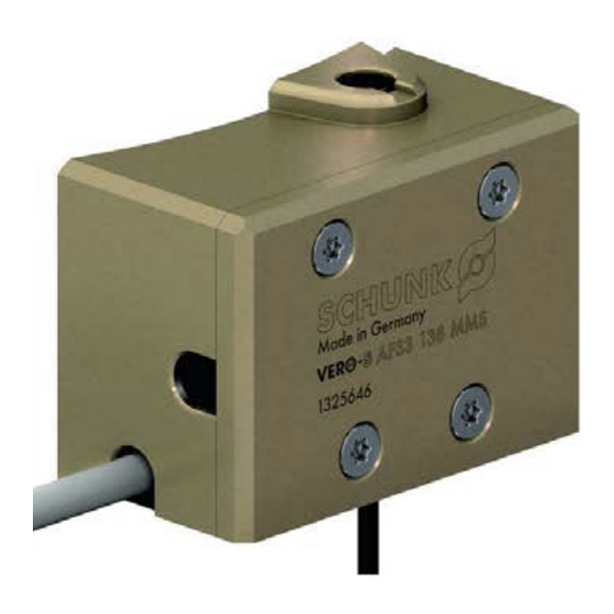
Page 13: Afs3 138 Mms
Function AFS3 138 MMS The AFS3 138 MMS is a compact monitoring unit with two monitoring control functions. It is fitted onto the housing of the clamping module in clamping slide axis via 2 mounting threads below the clamping slide bore holes and 2 M4 screws. The mounting location depends on the quick-change pallet system type. -
Page 14: General Installation Notes
General Installation Notes General Installation Notes The monitoring systems are intended to be used with the VERO-S NSE3 clamping module. Installation with the VERO-S NSE-T3 138 is not possible. For mounting, there are two mounting threads below the clamping slide on the outer circumference of the quick-change pallet module. -
Page 15: Mounting / Connection / Programming Of The Afs3 138 Pmi
138 PMI Installing the AFS3 138 PMI to the NSE 138 (-V1) (-K) The AFS3 138 PMI is installed on a VERO-S NSE3. The system is supplied partially assembled. Step-by-step installation instructions makes assembly of the multi-part monitoring unit easier. - Page 16 Mounting / connection / programming of the AFS3 138 PMI Installing the AFS3 138 PMI to the NSE3 138 (-V1) (-K) Installing the AFS3 138 PMI The unit is installed to a VERO-S NSE3 according to the following assembly steps 1 Select installation side on the quick-change pallet system.
-
Page 17: Connecting The Afs3 138 Pmi
Mounting / connection / programming of the AFS3 138 PMI 6 Unscrew monitoring rod with M5 screw on clamping pin. 7 Mount inductive position measuring system PMI on bracket, adjust to stop in direction of monitoring rod. Insert sensor cable in cable bushing and fix onto cable outlet of the bracket. Integrated sensors of the system into the control. - Page 18 Mounting / connection / programming of the AFS3 138 PMI Note: The programming device with order no. 9988354 that is required to program the position measuring system is available as additional accessory and is not included in the scope of delivery of the AFS3 138 PMI.
-
Page 19: Programming The Switching Positions For The Clamping Slide Monitoring With The Afs3 138 Pmi
Mounting / connection / programming of the AFS3 138 PMI Clamping slide Switching output S1 Switching output S2 position Open clamping module Closed without clamping pins clamping module Closed with clamping pallet clamping module; without turbo Closed with clamping pallet clamping module;... - Page 20 Mounting / connection / programming of the AFS3 138 PMI The switching positions are taught in with the teaching device (ID no.: 9988354) Connect sensor to teaching device Press the "Teach" button on the teaching device for 1.5 s (until LED S2 flashes) Put the clamping module in open status Press the button on the teaching device (LED S2 illuminates and...
-
Page 21: Signal Statuses After Teach-In Process For The Afs3 138 Pmi
Mounting / connection / programming of the AFS3 138 PMI Signal statuses after teach-in process for the AFS3 138 PMI Open clamping module Closed without clamping pins clamping module Closed with clamping pallet clamping module; without turbo Closed with clamping pallet clamping module; with 6 bar turbo Function test on the clamping module with connected, ready for operation AFS3 138 PMI The monitoring system can monitor 3 clamping positions:... -
Page 22: Mounting / Connection / Programming Of The Afs3 138 Mms
138 MMS Installing the AFS3 138 MMS to the NSE3 138 (-V1) (-K) The AFS3 138 MMS is installed on a VERO-S NSE3. The system is supplied partially assembled. Step-by-step installation instructions makes assembly of the multi-part monitoring unit easier. - Page 23 Mounting / connection / programming of the AFS3 138 MMS The unit is installed to a VERO-S NSE3 quick-change pallet system according to the following assembly steps 1 Select installation side on the quick-change pallet system. 2 Unscrew grub screw M5 clamping slide.
-
Page 24: Connecting The Afs3 138 Mms
Mounting / connection / programming of the AFS3 138 MMS permanently in the magnetic switch and can be readjusted if required. The programming tools are included in the scope of delivery, consisting of plastic bracket with magnetic insert and an Allen key to jam sensor in the housing of the AFS3 138 MMS. 15 Perform functional test of the electronic magnetic switch for the clamping slide monitoring. - Page 25 Mounting / connection / programming of the AFS3 138 MMS Optional accessories • Angular plug with feeder cable WK 3-M8 plug connection 3 meter cable length (individual): ID no.: 0301594 • Angular plug with feeder cable WK 5-M8 plug connection 5 meter cable length (Individual): ID no.: 0301502 Caution: •...
-
Page 26: Programming The Switching Positions For The Clamping Slide Monitoring With The Afs3 138 Mms
Mounting / connection / programming of the AFS3 138 MMS Programming the switching positions for the clamping slide monitoring with the AFS3 138 MMS For the AFS3 138 MMS, 2 switching positions are monitored. The switching positions are taught in with the teaching device (ID no.: 0301026) or with the supplied teach-in tool... -
Page 27: Signal Statuses After Teach-In Process For The Afs3 138 Mms
Mounting / connection / programming of the AFS3 138 MMS without turbo. Start teaching mode with teaching device or teach-in tool (2 sec. actuation time) Yellow LED flashes on the sensor Blue LED (A1) flashes on the teaching device Wait 10 sec. until the red LED on the sensor flashes and / or the blue LED (A2) flashes on the teaching device Wait 10 sec until the red diode on the sensor flashes and / or the blue LED (A2) on the teaching device flashes... -
Page 28: Function Test On The Clamping Module With Connected, Ready For Operation Afs3 138 Mms
Mounting / connection / programming of the AFS3 138 MMS Function test on the clamping module with connected, ready for operation AFS3 138 MMS The monitoring system can monitor 2 clamping positions: 1 Open clamping module (A1: 1 ; A2: 0) 2 Closed without clamping pallets clamping module (A1: 0;... -
Page 29: Maintenance And Care
Maintenance and care Maintenance and care Carry out regular visual / functional checks. In case of visible damage or signs of malfunction, shut down the system immediately. The system may only be commissioned again once the faults have been removed. For example, by replacing the damaged unit. -
Page 30: Troubleshooting
Troubleshooting Troubleshooting The AFS3 138 PMI is not working No control of switching valves due to missing signal output Possible cause Remedial measures Position measuring system for Check all screw connections of monitoring the clamping slide the sensor, as well as the target positions is not working mounting for correct seating. -
Page 31: The Afs3 138 Mms Is Not Working
Troubleshooting Proximity switch moves Tighten bracket according to independently tightening torque specification, check protective cover for damage and check collision contact to the proximity switch. Replace proximity switch type IN if required. Mechanical tensile force Check sensor cable for damage. influenced on connection cable Readjust sensor position and teach in switching window... - Page 32 Troubleshooting socket screwdriver. Check target for fixed jamming to the clamping slide. Check sensor head, attachment screw and installation groove for damage. Replace magnetic switch type MMS PI2 if required. Proximity switch not switching Readjust position. Adjust and tighten position and switching distance.
-
Page 33: Parts Lists
Parts lists Parts lists AFS3 138 PMI (ID no. 1325645) Item Characterization Quantity Holder Monitoring rod Protective cover Cover cap Sealing bush Grommets Nozzle for cable bushing Proximity switch bracket Inductive position measuring system Inductive proximity switches DIN 7984 cylindrical screw Cylindrical screw Cylindrical screw Flat lens head screw... -
Page 34: Assembly Drawings
Assembly Drawings Assembly Drawings 11.1 AFS3 138 PMI 01.00|1372106_AFS3 138 PMI_AFS3 138 MMS |en... -
Page 35: Afs3 138 Mms
Assembly Drawings 11.2 AFS3 138 MMS 01.00|1372106_AFS3 138 PMI_AFS3 138 MMS |en... -
Page 36: Sensor For Presence Monitoring Of The Clamping Pallet
SCHUNK contact persons. Technical data for the sensors can be found in the data sheets (included in the scope of delivery or under www.de.schunk.com). The used proximity and magnetic switches are protected against polarity reversal and short-circuit-proof. -
Page 37: Assembly, Connection, Technical Data Proximity Switch In60
Sensor for presence monitoring of the clamping pallet 12.1 Assembly, connection, technical data proximity switch IN60 Technical data Sensor IN-60-M8 with circular plug M8: ID no.: 0301485 Optional accessories • Angular plug with feeder cable WK 3-M8 plug connection 3 meter cable length (individual): ID no.: 0301594 •...
Need help?
Do you have a question about the VERO-S and is the answer not in the manual?
Questions and answers