
Related Manuals for SCHUNK AGE-F-XY Series


Summary of Contents for SCHUNK AGE-F-XY Series
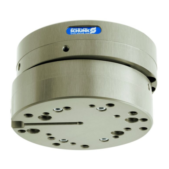
- Page 1 Original Operating Manual Assembly and Operating Manual AGE-F-XY Compensation unit with spring return...
- Page 2 Imprint Copyright: This manual is protected by copyright. The author is SCHUNK GmbH & Co. KG. All rights reserved. Any reproduction, processing, distribution (making available to third parties), translation or other usage - even excerpts - of the manual is especially prohibited and requires our written approval.
-
Page 3: Table Of Contents
Table of contents Table of contents General........................ 5 About this manual .................... 5 1.1.1 Presentation of Warning Labels ............... 5 1.1.2 Applicable documents ................ 6 Warranty ...................... 6 Scope of delivery .................... 6 Accessories ...................... 6 1.4.1 Sensors ..................... 6 Basic safety notes .................... 7 Intended use...................... - Page 4 Table of contents Maintenance ...................... 22 Maintenance interval .................. 22 Lubricants/Lubrication points (basic lubrication) .......... 22 Disassemble the module .................. 22 Maintaining and assembling the module ............ 23 Assembly drawing.................... 24 03.00 | AGE-F-XY | Assembly and Operating Manual | en | 389002...
-
Page 5: General
General 1 General 1.1 About this manual This manual contains important information for a safe and appropriate use of the product. This manual is an integral part of the product and must be kept accessible for the personnel at all times. Before starting work, the personnel must have read and understood this operating manual. -
Page 6: Applicable Documents
Programmable magnetic switch MMS22 • Exact type designation of the compatible sensors see catalog. • Information on handling sensors is available at schunk.com or from SCHUNK contact persons. 03.00 | AGE-F-XY | Assembly and Operating Manual | en | 389002... -
Page 7: Basic Safety Notes
Use of unauthorized spare parts Using unauthorized spare parts can endanger personnel and damage the product or cause it to malfunction. • Use only original spare parts or spares authorized by SCHUNK. 03.00 | AGE-F-XY | Assembly and Operating Manual | en | 389002... -
Page 8: Ambient Conditions And Operating Conditions
Basic safety notes 2.5 Ambient conditions and operating conditions Required ambient conditions and operating conditions Incorrect ambient and operating conditions can make the product unsafe, leading to the risk of serious injuries, considerable material damage and/or a significant reduction to the product's life span. •... -
Page 9: Personal Protective Equipment
Basic safety notes 2.7 Personal protective equipment Use of personal protective equipment Personal protective equipment serves to protect staff against danger which may interfere with their health or safety at work. • When working on and with the product, observe the occupational health and safety regulations and wear the required personal protective equipment. -
Page 10: Malfunctions
Basic safety notes 2.10 Malfunctions Behavior in case of malfunctions • Immediately remove the product from operation and report the malfunction to the responsible departments/persons. • Order appropriately trained personnel to rectify the malfunction. • Do not recommission the product until the malfunction has been rectified. -
Page 11: Protection During Commissioning And Operation
Basic safety notes WARNING Risk of injury due to uncontrolled movements! Due to faulty control the product can move uncontrolled and cause serious injuries. Do not reach into the movement range of the product during • commissioning, conversion and adjustment work. Observe the direction of rotation of the product when •... -
Page 12: Technical Data
Technical data 3 Technical data Size Recommended workpiece weight [kg] 12.5 32.3 Max. payload / load capacity F 2800 pull Max. payload / load capacity F 3000 12000 pressure Weight [kg] 0.123 0.23 0.78 3.13 Max. reset force [N] Version - 1 25.0 70.0 Version - 2... -
Page 13: Assembly And Settings
DIN 9409 element (optionally to be provided by 5 Handling device, e.g. gripper SCHUNK or by the customer) 6 Mounting screws for gripper • An interface plate with a hole pattern for locating holes is optionally available. • The adapter plate is screwed with the robot and AGE-F-XY (see catalog for mounting data). -
Page 14: Mechanical Connection
Assembly and settings 4.2 Mechanical connection WARNING Breakage due to faulty assembly possible! Observe max. screw-in depth on robot-side and on tool-side. Evenness of the The values apply to the whole mounting surface to which the product is mounted. mounting surface Requirements for evenness of the mounting surface (Dimensions in mm) Edge length Permissible unevenness... -
Page 15: Setting The Stop In Order To Limit Stroke
Assembly and settings 4.3 Setting the stop in order to limit stroke Set-screw (52) to limit stroke for type AGE-F-XY-40 Set-screw (52) to limit stroke for types AGE-F-XY-63/80 Dimensions of set-screw (52) AGE-F-XY Item Designation Thread diameter Minimum length [mm] 03.00 | AGE-F-XY | Assembly and Operating Manual | en | 389002... -
Page 16: Adjusting, Removing And Replacing The Return Spring For Units Built Before June 2016
Assembly and settings Insert set-screw or screw NOTICE The set-screw can fall into the housing if it is screwed in too far. The compensation unit can jam. Observe the minimum length of the set-screw! • Remove the set-screw (52) using a hexagon socket wrench. Ø... - Page 17 Assembly and settings The units are delivered ex-works with the following setting dimensions for the set-screws: Size Setting dimension for 10+0.2 13.5+0.2 17.7+0.2 18.5+0.2 Version 1 [mm] Setting dimension for 10+0.2 12.5+0.2 17.2+0.2 18.5+0.2 Version 2 [mm] Setting dimension for 9.3+0.2 12.5+0.2 15.2+0.2 18.5+0.2 Version 3 [mm] The catalog values have been ascertained in this basic setting.
-
Page 18: Adjusting, Removing And Replacing The Return Spring For Units Built In Or After June 2016
Assembly and settings 4.5 Adjusting, removing and replacing the return spring for units built in or after June 2016 The unit contains 4 compression springs for the return position function. The force values on the unit can not be changed anymore (applies to units delivered since June 2016). -
Page 19: Programmable Magnetic Switch (Mms-P)
Assembly and settings 4.6 Programmable magnetic switch (MMS-P) Magnetic switch MMS 22 brown closer load black blue Connection diagram NOTICE Risk of damage to the sensor during assembly. Observe a maximum tightening torque of 10 Ncm for the set- • screws. - Page 20 Assembly and settings Position of the magnetic switch MMS - stop position (A) The magnetic switches MMS are mounted and adjusted equally for each axis movement: Assembly steps Screw in the sensor Ø insert the sensor axially into the groove until the required signal is present.
-
Page 21: Troubleshooting
Troubleshooting 5 Troubleshooting 5.1 Module does not move? Possible cause Corrective action Setscrew/stop screw screwed in too deep Use a shorter stop screw Setting the stop in order to limit stroke 15] Setscrew for spring adjustment screwed in Turn back the setscrew (50) Adjusting, too far removing and replacing the return spring for... -
Page 22: Maintenance
Reduce the lubricant intervals accordingly. • Interval [Mio. cycles] 6.2 Lubricants/Lubrication points (basic lubrication) SCHUNK recommends the lubricants listed. During maintenance, treat all greased areas with lubricant. Thinly apply lubricant with a lint-free cloth. Lubricant point Lubricant... -
Page 23: Maintaining And Assembling The Module
Maintenance Remove the setscrews (50) from the guide cross (3) in order to Ø be able to access the return springs (15). Take the guide sleeves (4) out of the guide cross (3). Ø NOTICE Loss of precise repeat accuracy The setscrews (40) are glued in firmly and carefully aligned. -
Page 24: Assembly Drawing
Maintenance 6.5 Assembly drawing The following figure is an example image. It serves for illustration and assignment of the spare parts. Variations are possible depending on size and variant. 03.00 | AGE-F-XY | Assembly and Operating Manual | en | 389002...
Need help?
Do you have a question about the AGE-F-XY Series and is the answer not in the manual?
Questions and answers