
Related Manuals for Magnescale mMATE+ LU20


Summary of Contents for Magnescale mMATE+ LU20
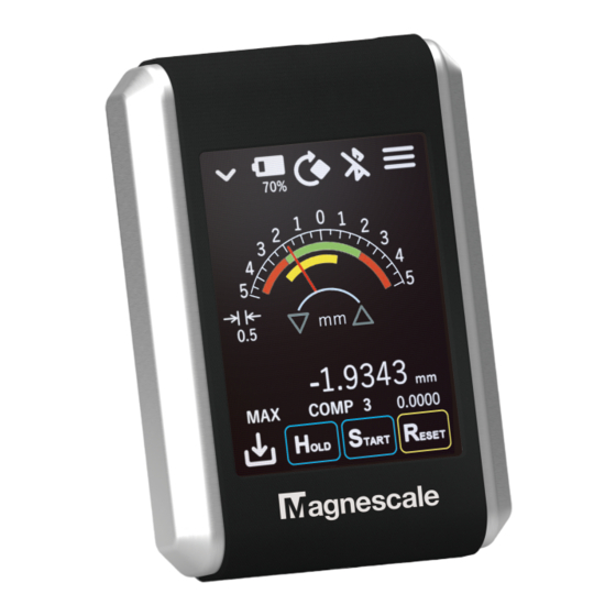
- Page 1 Digital Indicator LU20 (F) Read all the instructions in the manual carefully before use and strictly follow them. Be sure to keep this manual for future reference. Operating Manual...
- Page 2 ・ In no event will Magnescale Co., Ltd. or its suppliers be liable to you for any consequential or inconsequential damages, including any lost profits or lost savings or any claims made by a third party arising out of use of the unit or the software supplied with the unit described in this manual.
- Page 3 RISK OF FIRE dedicated accessory DZ60 (sold separately) In no event will Magnescale Co., Ltd. be liable to you for any accident or malfunction arising out of use of batteries other than the dedicated batteries. ・ When charging the batteries, do not remove them from the LU20. Be sure FORCE to charge the batteries via the LU20 main unit.
-
Page 4: Table Of Contents
Contents Before use ......................1 1-1. General precautions ..................1 1-2. Handling precautions ..................1 Outline ......................2 2-1. System configuration ..................2 Name and function of each part ................3 3-1. Name of each part ................... 3 3-2. Charging......................3 3-3. -
Page 5: Before Use
Before use 1-1. General precautions When using Magnescale Co., Ltd. products, observe the following general precautions along with those given specifically in this manual to ensure proper use of the products. ・ Before and during operations, be sure to check that our products function properly. -
Page 6: Outline
Outline The LU20 is a digital indicator that can be used in combination with a DM series digital lever gauge (in development) or DS series digital gauge to display and save measurement data, make various settings, and communicate with a host device via Bluetooth or USB. 2-1. -
Page 7: Name And Function Of Each Part
Name and function of each part 3-1. Name of each part Connector for charging or Measuring unit connector connecting a PC (USB Type-A) (USB Type-C) Battery cover Power button Operation screen microSD card slot 3-2. Charging 3-2-1. Open the rubber cover of the charging connector (USB Type-C). 3-2-2. - Page 8 3-2-3. After charging, firmly close the rubber cover. Rubber cover CAUTION Do not apply excessive force when connecting and disconnecting the connector. Reference ・ Power can also be supplied from a commercially available USB charger (10 W or more) or a ・...
-
Page 9: Installation With The Mounting Stand
3-3. Installation with the mounting stand CAUTION The accessory mounting stand uses a strong magnet. Be careful as if electronic devices, magnetic recording media, or magnetic cards, etc. are brought close to it, recorded contents may be destroyed or items may become magnetized, making them unusable. -
Page 10: Installation Using The Main Unit Mounting Hole
3-4. Installation using the main unit mounting hole The bottom of the main unit can be fixed by a screw. CAUTION ・ The mounting hole on the bottom face of the LU20 main unit is M3 depth: 4.5 mm. In consideration of the mounting screw length and the dimension of the mating mounting part, the screwing depth should not exceed 4.5 mm and a tightening torque of 0.3 N・m. -
Page 11: Turning The Power On And Off
3-5. Turning the power ON and OFF ・ Power ON Press the Power button until a beep sounds. The operation screen display appears. ・ Power OFF Press the Power button until a beep sounds. The operation screen display disappears. Power button 3-6. -
Page 12: Inserting And Removing A Microsd Card
3-7. Inserting and removing a microSD card Slide the cover in the direction of arrow A to open it. Cover 3-7-1. Inserting a microSD card Open the cover and insert the microSD card straight into the slot facing as illustrated. When inserting the microSD card, push it in Until it clicks. -
Page 13: Battery Replacement
3-8. Battery replacement Warning ・ Be sure to use our dedicated batteries supplied with the product or our dedicated accessory DZ60 (sold separately). Failure to use the dedicated batteries may lead to fire, electric shock, or other accidents resulting in injury or death. ・... - Page 14 3-8-3. Install two new batteries. Warning ・ Make sure the plus and minus directions are correct when installing the batteries. Battery Battery 3-8-4. Mount the battery cover with the two screws. Battery cover Battery Screw...
-
Page 15: Operation
Operation 4-1. Screen outline The screen has the following three areas. Operations are performed by touch panel operations. Main menu area Measurement area Operation area... -
Page 16: Main Menu Area
4-2. Main menu area ① ② ③ ④ ⑤ Button Status Button Status Button indication indication ① Show/hide submenu area button Shows and hides the submenu area. * For details of the submenu area, refer to “4-3. Submenu area”. Submenu area ②... - Page 17 ③ Rotate screen button The measurement area rotates 90° in the clockwise direction each time the button is tapped. ④ Bluetooth status indicator Indication Description Indicates the Bluetooth status. Bluetooth OFF Bluetooth ON/OFF is set by Setup screen: System - Bluetooth. Bluetooth ON, connection not established Bluetooth ON, connection...
-
Page 18: Submenu Area
4-3. Submenu area Button Button Button Button ① ② ③ ④ ⑤Button ⑥Button ⑦Button ⑧ ① Switch display mode button Indication Description The measurement area display mode switches Dial display mode each time the button is tapped. Bar meter display mode Numeric display mode Trend chart display mode Simple circle measurement... - Page 19 Numeric display mode Dial display mode Bar meter display mode Reproduces the Displays the same Numerically displays the movement of a needle information as dial current value, maximum such as when using a display mode using a bar value, minimum value, lever gauge or dial gauge.
- Page 20 ② Show device information button Displays the information of the Setup screen: System - Sensor ID screen. This enables to quickly check the device information. ③ Remove microSD card button Indication Description Tap this button in the microSD card connected Disconnected state state to end the connection.
- Page 21 ⑥ Comparator set number switching button Switches the comparator setting set used to perform Go/No Go judgment on measurement values. There are ten comparator sets. Select from comparator OFF and comparator 1 to 10. ︓ Comparator OFF ~ ︓Comparator set 1 to comparator set 10 The upper and lower limit values are set by Setup screen: Measure - Comparator.
-
Page 22: Measurement Area
4-4. Measurement area 4-4-1. Common area ① Absolute position bar indicator ② Comparator set number display ④ Compensation indicator ③ Measurement mode display ⑤ Preset value display ① Absolute position bar indicator The position of the measuring unit relative to the measuring range can be checked. Use within the green range. - Page 23 4-4-2. Dial display mode ① Upper/lower limit area indicator ② P-P value display ③ Display range switching ⑤ Measurement value button sub display ④ Measurement value display ① Upper/lower limit area indicator The range within the upper and lower limit values of the measurement values for the selected comparator set number is indicated by green, and outside that range is indicated by red.
- Page 24 4-4-3. Bar meter display mode ① Current value display ② P-P value display ⑤ Measurement value sub ③ Display range switching button display ④ Measurement value display ① Current value display Displays the current value with a bar graph. The range within the upper and lower limit values of the current value for the selected comparator set number is indicated by green, and outside that range is indicated by red.
- Page 25 4-4-4. Numeric display mode Displays four measurement values: current value, maximum value, minimum value, and P-P value. Values outside the upper and lower limit value ranges for the selected comparator set number are displayed in red. 4-4-5. Trend chart display mode ②...
- Page 26 4-4-6. Simple circle measurement display mode ② Change rotation speed button ① Change measurement value range button ③ Start/Stop drawing button ① Change measurement value range button The measurement value drawing range can be changed. ② Change rotation speed button Sets the workpiece rocation speed in rpm units.
-
Page 27: Operation Area
4-5. Operation area ② ③ ④ ① ① Data Save button This is used to send measurement values to a host device such as a smartphone, tablet PC, or PC, and to save measurement values on a microSD card. ② HOLD button Stops updating of the four measurement values: current value, maximum value, minimum value, and P-P value. - Page 28 ④ RESET/PRESET button Indication Description Long-press the button to set the preset value. RESET indication When the preset values are 0, the button indication is The preset values are 0. “RESET”, and when the preset values are other than 0, PRESET indication the button indication is “PRESET”.
-
Page 29: Bluetooth Communication
4-6. Bluetooth communication 4-6-1. App mode In App mode, the LU20 communicates with a dedicated app on a host device such as a smartphone, tablet PC, or PC. The LU20 can be operated from the dedicated app. Refer to the Instruction Manual of each app for how to connect in App mode. Setup screen: System - Bluetooth 4-6-2. - Page 30 ② Open Windows Settings on the PC to connect with the LU20, then open “Devices”. ③ Select “Bluetooth & other devices”, and turn on “Bluetooth”. ④ Select “Add Bluetooth or other device” and look for the LU20. The name found here is “HID-” + Sensor ID. In HID mode, “HID-”...
- Page 31 The Sensor ID is the name assigned to the connected measuring unit, and can be edited at the following screen. Setup screen: System - Sensor ID * The Sensor ID contents are stored in the measuring unit. How to disconnect from a Windows PC (for Windows 10) ...
- Page 32 ③ Set Bluetooth Mode of the LU20 to OFF. ④ Clear the pairing data. If the pairing data with the connected PC is not cleared, connection with another PC will not be possible. * To disconnect only temporarily, perform only step ③. When not connecting again after disconnection, perform steps ①...
- Page 33 How to input data Open the application to which the data will be input beforehand on the PC. ・ One-shot save ① Set the Timer save setting to OFF. Setup screen: Data Save - Mode ② Tap the Data Save button. The measurement values are input each time the Data Save button is tapped.
- Page 34 ・ Timer save ① Set the Timer save setting to ON. ② Tap the Data Save button to start and stop the timer. * Make sure that the keyboard input setting of the PC is set to single-byte alphanumeric input. * “_”...
- Page 35 Data format 2023/04/05 09:48:44,DM10-01_100001,1.0000,1.0009,0.9999,0.0010 ① ② ③ ④ ⑤ ⑥ ① Saved date and time information. YYYY/MM/DD hh:mm:ss Added when “TimeStamp” on the Setup screen: Data Save - HID Format is turned on. ② Sensor ID of the measuring unit used for measurement. Added when “Sensor ID”...
-
Page 36: Saving Measurement Data On A Microsd Card
4-7. Saving measurement data on a microSD card ・ Refer to “3-7. Inserting and removing a microSD card” for how to insert and remove a microSD card. ・ To check the microSD card insertion status, refer to “4-3. Submenu area”. How to save data ... - Page 37 ・ Timer save ① Set the Timer save setting to ON. ② Tap the Data Save button to start and stop the timer. Setting items For details, refer to “5. Settings”. The following Setup screens are related to saving measurement data on a microSD card. ・...
- Page 38 Data format A measdata folder is automatically created on the microSD card, and a CSV file is created in the measdata folder. ・ File name [LU20 model name]+[LU20 serial number].csv Example: LU20(F)_123456.csv ・ Data format 1,2023/04/05 09:48:44,DM10-01_100001,1.0000,1.0009,0.9999,0.0010 ① ② ③...
-
Page 39: Settings
Settings Various settings and operations can be performed on the Setup screen. Tap the Go to Setup screen button in the main menu area to open the Setup screen. Indication Description Measure Settings related to measurement. Data Save Settings related to saved data and HID output. - Page 40 5-1-1. Resolution Indication Description Direction Selects the count direction (+/-). Resolution Selects the display resolution. Measurement values are displayed and saved in the display resolution units. In mm/μm unit display: 0.1 μm / 0.5 μm / 1.0 μm / 5.0 μm / 10.0 μm In inch unit display: 0.001 thou / 0.005 thou / 0.01 thou /...
- Page 41 5-1-3. Adjustment Indication Description Scaling An arbitrary scaling factor can be applied to the measurement values. 0.0001 to 10.0000 Angle This enables to compensate error due to the angle at which the stylus or spindle contacts the workpiece. The following calculation result is used as the measurement value.
-
Page 42: Data Save
5-2. Data Save Indication Description Mode Timer save and save item settings. HID Format Data format setting for key input of measurement values as an HID keyboard device. SD Format Data format setting when saving measurement values on a microSD card. - Page 43 5-2-2. HID Format Settings related to HID keyboard input. Indication Description Sensor ID Set to ON to add the Sensor ID to the input data. TimeStamp Set to ON to add the date and time information to the input data. Delimiter Selects the delimiter character between each data.
-
Page 44: System
5-3. System Indication Description Bluetooth Bluetooth settings. Sensor ID Measuring unit information settings. Sensor Spec Measuring unit specification settings. 5-3-1. Bluetooth Indication Description Bluetooth Mode Sets the Bluetooth mode. OFF: Bluetooth OFF HID: HID keyboard. App: App connection mode. Pairing Data Tap the Clear button to delete the pairing data. - Page 45 5-3-2. Sensor ID Indication Description Sensor ID An arbitrary name can be assigned to the measuring unit. This information is stored in the measuring unit. Max. 16 characters Available characters Common: [A to Z], [a to z], [0 to 9] DM series: [+-.&()=@~] DS series: [-.] First character is alphabetic only...
-
Page 46: Hardware
5-4. Hardware Indication Description Buzzer Settings related to the buzzer. Settings related to the LCD. Power Save Settings related to the power save timer. 5-4-1. Buzzer Indication Description Volume Sets the buzzer volume in three levels. 1 (Low) / 2 (Medium) / 3 (High) Buzzer Item Selects the conditions for sounding the buzzer. - Page 47 5-4-2. Indication Description Brightness Selects the screen brightness. 25% / 50% / 75% / 100% * The brighter the screen, the faster the battery charge is consumed. 5-4-3. Power Save Indication Description Sleep Mode If there is no operation for the set period of time in the operating state, the device(s) will enter sleep mode.
-
Page 48: Info
5-5. Info Indication Description Indicator The information of the LU20 digital indicator can be set and referenced. Sensor The information of the measuring unit can be set and referenced. 5-5-1. Indicator Indication Description Indicator Info The information of the LU20 digital indicator can be referenced. - Page 49 5-5-1-2. Maintenance Indication Description Hours Cumulative operating time of the LU20 digital indicator. This can be reset on the Admin Menu screen. Total Hours Cumulative operating time of the LU20 digital indicator. This cannot be reset.
- Page 50 5-5-1-3. Admin Menu Indication Description Hours Reset Resets the cumulative operating time of the LU20 digital indicator. Factory Reset Resets the LU20 digital indicator settings to the factory settings. Use Password Set to ON to use the Setup screen password lock function.
- Page 51 5-5-2. Sensor Indication Description Sensor Info The information of the measuring unit can be referenced. Maintenance The maintenance information of the measuring unit can be referenced. Admin Menu The administrator settings of the measuring unit can be controlled. All Sensor setting information is stored in the measuring unit.
- Page 52 5-5-2-2. Maintenance These settings are available only with a DM series measuring unit. Indication Description CAL Date The next calibration date can be referenced. It can be edited on the Admin Menu screen. Hours Cumulative operating time of the measuring unit. This can be reset on the Admin Menu screen.
-
Page 53: Clock
5-6. Clock Sets the date and time. CAUTION When the battery level becomes extremely low or the batteries are removed, the internal clock is reset and must be set again. -
Page 54: Factory Settings
5-7. Factory settings Item Setting value Measure Resolution Direction + Resolution 0.1 μm Comparator -0.0300 mm 0.0300 mm 0.0600 mm Adjustment Scaling 1.0000 Angle 0° Display Sub Value Data Save Mode Timer Interval 0.5 s Count Save Item Real HID Format Sensor ID TimeStamp Delimiter... - Page 55 Item Setting value Hardware Buzzer Volume Buzzer Item Button Save Comp Real Comp P-P Brightness Power Save Sleep Mode Sleep Device OFF Mode Info Indicator IndicatorInfo Model Maintenance Hours Total Hours AdminMenu Hours Reset Factory Reset Use Password Password 1111 CAL Notice Sensor SensorInfo...
-
Page 56: Errors
Errors 6-1. Alert messages The following alert messages are displayed when operation cannot continue normally. Message Cause Action SD system error 1 Data save to the microSD card If the error occurs repeatedly, failed. replace the microSD card. SD system error 2 MicroSD card mounting failed. -
Page 57: Measuring Unit Errors
6-2. Measuring unit errors When the measurement values of the measuring unit cannot be acquired normally, the measurement value display changes as follows. ・ When the measuring unit is not connected or measurement values cannot be acquired due to a communication error. -
Page 58: Specifications
Specifications 7-1. Product specifications Model LU20 Display / Touch panel TFT liquid crystal 2.7-inch QVGA 240 × RGB × 320 / Resistive film type Compatible measuring DM series, DS series (USB2.0FS Type-A) units Input/output interface USB2.0FS Type-C Wireless Bluetooth5.2 (Bluetooth Low Energy) Frequency band: 2402 MHz to 2480 MHz Power Class: Class1.5 Data storage media... - Page 59 *3 When operating and charging the main unit at the same time *4 Use our dedicated batteries supplied with the product. The batteries are replaceable. Use our dedicated accessory DZ60 (sold separately). *5 Varies according to the method of use and the battery status. *6 The structure is not bend resistant or oil resistant.
-
Page 60: Dimensions Diagrams
7-2. Dimensions diagrams 7-2-1. LU20 M3 depth 4.5 Unit: mm... - Page 61 7-2-2. Mounting stand Unit: mm...
- Page 63 容 ( 操作、保守など ) と異なる目的で本マニュアルを使用 することを禁止します。 The material contained in this manual consists of information that is the property of Magnescale Co., Ltd. and is intended solely for use by the purchasers of the equipment described in this manual. Magnescale Co., Ltd. expressly prohibits the duplication...
- Page 64 Note: Th is product (or technology) may be restricted by the government in your country. Please make sure that end-use, end user and country of destination of this product do not violate your local government regulation. 45 Suzukawa, Isehara-shi, Kanagawa 259-1146, Japan LU20 (F) 2024.1 2-A03-606-1A Printed in Japan ©2024 Magnescale Co., Ltd.
Need help?
Do you have a question about the mMATE+ LU20 and is the answer not in the manual?
Questions and answers