Paradyne 9261 Installation Instructions Manual
Zhone 9261 access module: install guide
Hide thumbs
Also See for 9261:
- Installation instructions manual (13 pages) ,
- User manual (324 pages) ,
- Reference manual (278 pages)
Table of Contents
Advertisement
Quick Links
9261 Dual T1 Network Access Module (NAM)
Installation Instructions
Document Number 9261-A2-GN10-00
September 1997
Before You Begin
Make sure you have:
An operable T1 network connection
An async (VT100-compatible) terminal emulation
Housing and other associated hardware
Applicable cables
Package Checklist
Verify that your package contains the following:
T1 NAM and associated I/O card
Affidavit Requirements for Connection to Digital Service
Warranty
Safety, Regulatory, Warranty and Service Information
(Document No. 9000-A2-GX41)
Available Option
The following option is separately orderable:
RJ48C modular cable for network access (14 )
TM
1
Advertisement
Table of Contents

Related Manuals for Paradyne 9261


Summary of Contents for Paradyne 9261
- Page 1 9261 Dual T1 Network Access Module (NAM) Installation Instructions Document Number 9261-A2-GN10-00 September 1997 Before You Begin Make sure you have: An operable T1 network connection An async (VT100-compatible) terminal emulation Housing and other associated hardware Applicable cables Package Checklist...
-
Page 2: Cables You May Need To Order
The T1 NAM acts as an interface between the T1 digital network and the customer premises equipment, converting signals received from the DTE to bipolar signals that can be transmitted over T1 and Fractional T1 lines. The 9261 T1 NAM also provides an additional T1 network interface connector. Typical applications include:... -
Page 3: Recommended Order Of Installation
Recommended Order of Installation 1. First, install the I/O card. 2. Connect all cables into the I/O card. 3. Install the NAM. 4. Go to the 2-Slot Housing Installation Instructions (Document No. 9000-A2-GN15), 5-Slot Housing with AC Power Supply Installation Instructions (Document No. -
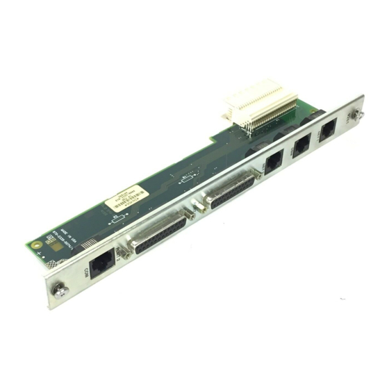
Page 4: Installing The I/O Card
Installing the I/O Card The NAM’s I/O card provides the COM port, network, and DTE connections. The I/O card inserts directly behind the NAM that it supports. Slot numbers are identical (in this case, Slot 01) to facilitate correct installation. 1. -
Page 5: Connecting To The Network
Connecting to the Network 1. Insert the 8-pin connector on the RJ48C network cable into the NET 1 and/or NET 2 interface. 2. Insert the other end of the cable into the RJ48C modular jack. Connecting to a DTE If the DTE cable type is V.35, RS449, or V.11/X.21 (separately orderable): 1. - Page 6 Connecting the COM Port to a User Interface 1. Insert the 8-pin end of the cable into the COM port. 2. Insert the other end of the cable into the user interface (VT100-compatible terminal emulation) connector. 3. Press Return on the keyboard to display the Main Menu. If you need to configure for other than a direct link, see the Technical Reference .
- Page 7 Installing the T1 NAM WARNING: Do NOT remove any jumpers located on the battery. To do so can cause non-volatile memory loss. Should a jumper become separated from the battery, contact your service representative immediately. HANDLING PRECAUTIONS FOR STATIC-SENSITIVE DEVICES This product is designed to protect sensitive components from damage due to electrostatic discharge (ESD) during normal operation.
- Page 8 4. Slide into the tracks until the NAM seats with the midplane connectors. Be careful not to force the card or bend any pins. 5. Close both the upper and lower ejector latches on the housing to lock in place, then tighten the captive screws on the ejector latches.
- Page 9 Removing/Replacing the I/O Card 1. Remove the NAM from the housing (see 2. Remove the network, DTE, and COM port cables from the I/O card (if applicable). 3. Using a screwdriver, loosen the upper and lower screws fastening the card to the housing’s frame.
- Page 10 Front Panel LEDs and Test Jacks The T1 NAM has 12 LED (light-emitting diode) status indicators and four sets of test jacks. Test Jacks The NAM contains four sets of test jacks. Use these for: Refer to Troubleshooting and Maintenance in the Technical Test Reference for more information on the test jacks.
- Page 11 Network 1 and Network 2 Interface LEDs Label Indication Signal Out of Frame Alarm Port 1 and Port 2 LEDs Label Indication 1-OK Operational 2-OK Status Color What It Means Green ON – A recoverable signal is present on the Network 1/Network 2 interface. OFF –...
-
Page 12: Troubleshooting
Troubleshooting Symptom No power, or none of the system LEDs are lit. Power-Up Self-Test fails. Only Alarm LED is on after power-up. Cannot access the NAM or the user interface. Device Fail appears on the System Health and Status screen. Not receiving data at DTE interface. -
Page 13: Technical Specifications
Technical Specifications Specification Weight T1 NAM T1 I/O card Size T1 NAM T1 I/O card Power Consumption Physical Environment Operating temperature Storage temperature Relative humidity Shock and vibration Network 1/2 T1 Interface Physical Interface (USA) Physical Interface (Canada) Framing Format Coding Format Line Build-Out (LBO) ANSI PRM... -
Page 14: Pin Assignments
Specification Clocking Sources Loopbacks Standard Additional Pin Assignments NET 1/2 Ports/Interfaces Function Receive ring from the network Receive tip from the network Transmit ring to the network Transmit tip to the network COM Port/Interface Signal DCE Transmit Clock ( TXC ) DCE Receive Data ( RXD ) Signal Ground ( SG ) DCE Transmit Data ( TXD ) - Page 15 DTE Ports/Interfaces Signal Shield Transmitted Data ( TXD ) Received Data ( RXD ) Request to Send ( RTS ) Clear to Send ( CTS ) Data Set (or DCE ) Ready ( DSR ) Signal Ground/Common ( SG ) Received Line Signal Detector ( RLSD or LSD ) Transmit Signal Element...
Need help?
Do you have a question about the 9261 and is the answer not in the manual?
Questions and answers