Table of Contents
Advertisement
Quick Links
Getting started with the STEVAL-SMARTAG2 NFC dynamic tag sensor and
Introduction
The
STEVAL-SMARTAG2
is an NFC-enabled sensor node, which embeds inertial MEMS sensors and environmental sensors,
an STM32 microcontroller, and a dynamic NFC tag for communication with NFC readers, such as tablets and smartphones.
The
STEVAL-SMARTAG2
can optionally be equipped with a battery charger fed through a full-wave rectifier for NFC energy
harvesting (to be put on top of the energy harvester already embedded in the dynamic NFC tag), a secure element to support
authentication and state-of-the-art cryptographic security, and a real-time clock (RTC) with an embedded crystal oscillator to
enable an accurate timekeeping and time stamping.
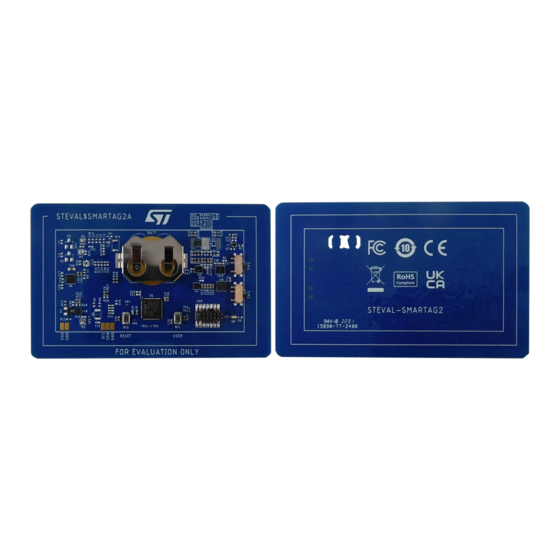
The board has a small and thin form factor, comparable to the size of a credit card. This makes it particularly fit for deployment
in the field and data collection.
Figure 1.
UM3034 - Rev 1 - October 2022
For further information contact your local STMicroelectronics sales office.
STEVAL-SMARTAG2 evaluation board (top and bottom views)
processing node evaluation board
UM3034
User manual
www.st.com
Advertisement
Table of Contents

Related Manuals for ST STEVAL-SMARTAG2


Summary of Contents for ST STEVAL-SMARTAG2
-
Page 1: Figure 1. Steval-Smartag2 Evaluation Board (Top And Bottom Views)
UM3034 User manual Getting started with the STEVAL-SMARTAG2 NFC dynamic tag sensor and processing node evaluation board Introduction STEVAL-SMARTAG2 is an NFC-enabled sensor node, which embeds inertial MEMS sensors and environmental sensors, an STM32 microcontroller, and a dynamic NFC tag for communication with NFC readers, such as tablets and smartphones. -
Page 2: Getting Started
UM3034 Getting started Getting started Safety operating use and conditions Any use of this device not specified by the manufacturer might compromise the protection mechanisms that come with the device. • All components, with few exceptions, have an operating temperature range from -40 to +85°C. Some components, such as the STM32L4P5CG microcontroller and the... - Page 3 UM3034 Safety operating use and conditions • LIS2DUXS12 – Operating conditions: temperature -40 to +85°C, acceleration up to 16 g. – Absolute maximum ratings: voltage -0.3 to 4.3 V, storage temperature -40 to +125°C, acceleration 10’000 g for 0.2 ms, 3000 g for 0.5 ms. •...
-
Page 4: Overview
UM3034 Overview Overview Figure 2. STEVAL-SMARTAG2 components Note: Components highlighted in yellow are populated at the factory. Components highlighted in gray are optional. STEVAL-SMARTAG2 components • ST25DV64KC-JF6D3 dynamic NFC/RFID tag with a 64-Kbit EEPROM, fast transfer mode capability, and an operating band of 13.56 MHz (HF). It is a two-wire I²C serial interface (up to 1 MHz), with a contactless interface based on the ISO/IEC 15693 (all modulations, coding, sub-carrier modes, and data rates). - Page 5 UM3034 Overview • Inertial sensors: – LSM6DSO32X inertial module (iNEMO) with 6DoF (degrees of freedom): three-axis accelerometer (4, 8, 16, 32 g full-scale) and three-axis gyroscope (125, 250, 500, 1000, 2000 dps full scale). The peak power consumption is 0.55 mA for the accelerometer and gyroscope in the high-performance mode at 6.6 kHz output data rate (ODR) and can be reduced down to 4.4 µA for the accelerometer only in the ultra-low power mode at 1.6 Hz ODR.
- Page 6 • Flash/debug 14-pin connector to be used with an ST-LINK in-circuit debugger/programmer. STEVAL-SMARTAG2 optional components • LSM6DSO32X configured as a sensor hub: the I²C bus interface of each environmental sensors (excluding the ambient light sensor) can be re-routed to the LSM6DSO32X, which is equipped with an auxiliary I²C bus interface.
- Page 7 UM3034 Overview • STBC15 ultra-low current consumption linear battery charger. It is bases on a constant current and constant voltage (CC/CV) charging algorithm. It embeds overdischarge and overcurrent protections to protect the battery. The device can be put in shelf-mode, consuming only 10 nA and not discharging the battery before the activation.
-
Page 8: Rf Specifications For The St25Dv64Kc
Channel spacing: the tag receives on a unique channel Battery insertion/removal Insert/remove the battery as shown below. Figure 3. STEVAL-SMARTAG2 - battery insertion/removal Important: To make the board operate correctly, ensure that the battery is inserted with the positive pole up. UM3034 - Rev 1... -
Page 9: System Architecture
(typical 0.84 µA, maximum 1.5 µA). Figure 4. STEVAL-SMARTAG2 architecture and communication paths Components highlighted in yellow are populated at the factory. Components highlighted in gray are optional. Inertial sensors have a dedicated SPI bus interface (SPI1). This SPI supports a faster communication speed (up to 10 Mbps) with respect to the I²C. -
Page 10: Rf Communication Performance
UM3034 RF communication performance • GPIO1, INT_TEM, and INT_PRE interrupt lines respectively from VD6283TX ambient light sensor, STTS22H contact temperature sensor, and LPS22DF ambient pressure sensor. Note: When the microcontroller supplies power to other components in the system, follow specific sequences to enable/disable the SPI interface and use the CS chip select. -
Page 11: Power Path Configuration
Battery mode: the CR2032 must be present and its voltage must be higher than the voltage of the V_EH line. Figure 5. STEVAL-SMARTAG2 power path Components highlighted in yellow are populated at the factory. Components highlighted in gray are optional. ST25DV64KC NFC EEPROM can be powered via the NFC field or via the dedicated line from the microcontroller (VDD_EEP). -
Page 12: Power-On And Power-Off Sequences
UM3034 Power-on and power-off sequences • The additional energy harvester consists of a chain of tuning inductors or 0 R resistors, four diodes in a full-wave rectifier configuration, MOSFETs for power gating, a capacitor bank for energy storage, and a Zener diode for the overvoltage protection. -
Page 13: Programming And Debugging
UM3034 Programming and debugging Programming and debugging System requirements To program and debug the STEVAL-SMARTAG2, you need: • STLINK-V3MINI in-circuit debugger • a GUI utility (STM32CubeProgrammer) to program the target microcontroller through the in-circuit debugger • a serial terminal emulator such as... -
Page 14: How To Program The Board With Stm32Cubeprogrammer
How to program the board 4.2.1 How to program the board with STM32CubeProgrammer Step 1. Select ST-LINK from the pull-down menu in the top left corner. Then, press the [Connect] button. Figure 7. Selecting ST-LINK and connecting the board Step 2. -
Page 15: Figure 9. Browse And Start Programming
UM3034 How to program the board Step 3. Press [Browse] to navigate the file system, select, and open the binary program. Then press [Start Programming] and wait for the process to be completed. Figure 9. Browse and start programming Step 4. Press [OK] to acknowledge the completion of the programming process. -
Page 16: How To Display The Firmware Output Using Tera Term
How to display the firmware output using Tera Term Step 1. Select [File][New Connection]. Figure 11. New connection selection Step 2. Select the COM port associated with the ST-LINK and confirm with [OK]. Figure 12. COM port selection Step 3. Select [Setup]>[Serial Port]. Figure 13. -
Page 17: Figure 14. Serial Port Configuration
Configure the serial port parameters as shown in the figure below. Figure 14. Serial port configuration Note: To enable/disable this UART functionality on the STEVAL-SMARTAG2 board, you must recompile the code by uncommenting/commenting the line: #define SMARTAG2_ENABLE_PRINTF in the Projects\ STM32L4P5CE-SmarTag2\Examples\SmarTag2\Inc\SMARTAG2_config.h file. -
Page 18: Figure 15. Fp-Sns-Smartag2 Uart Output Initialization
UM3034 How to program the board Figure 15. FP-SNS-SMARTAG2 UART output initialization After the auto-start range time, the samples are logged using the written configuration on the NFC tag (or the default one, if not available). UM3034 - Rev 1 page 18/38... -
Page 19: Figure 16. Fp-Sns-Smartag2 Uart Output Auto-Start
UM3034 How to program the board Figure 16. FP-SNS-SMARTAG2 UART output auto-start When the smartphone is close to the NFC tag, the message "Detected NFC FIELD On" appears. UM3034 - Rev 1 page 19/38... -
Page 20: Figure 17. Fp-Sns-Smartag2 Uart Output Nfc On
UM3034 How to program the board Figure 17. FP-SNS-SMARTAG2 UART output NFC on When the smartphone is kept distant from the NFC tag, the message "Detected NFC FIELD Off" appears together with the new configuration if a new one is detected. UM3034 - Rev 1 page 20/38... -
Page 21: Figure 18. Fp-Sns-Smartag2 Uart Output Nfc Off
UM3034 How to program the board Figure 18. FP-SNS-SMARTAG2 UART output NFC off UM3034 - Rev 1 page 21/38... -
Page 22: Schematic Diagrams
Schematic diagrams Figure 19. STEVAL-SMARTAG2 circuit schematic (1 of 6) I2C2_SDA I2C2_SCL IRQ/RTC M41T62LC6F 100n VBAT VDD2 INT_PRE PC13 VSS2 SWDIO PC14-OSC32_IN PA13 ISET0 SPI1_MOSI PC15-OSC32_OUT PA12 IMU_CS SPI1_MISO PH0-OSC_IN PA11 IRQ/RTC USART1_RX PH1-OSC_OUT PA10 NRST USART1_TX NRST I2C3_SCL VSSA... -
Page 23: Figure 20. Steval-Smartag2 Circuit Schematic (2 Of 6)
Figure 20. STEVAL-SMARTAG2 circuit schematic (2 of 6) SPI1_SCK VDD_ACC SCL/SPC VDD_IO ACC_CS VDD_ACC SPI1_MISO SDO/SA0 GND2 SPI1_MOSI SDA/SDI/SDO 100n 100n LIS2DUXS12TR SPI1_MISO SDO/SA0 SDO_AUX I2CX_SDA OCS_AUX Accelerometer I2CX_SCL ACC_INT2 INT2 ACC_INT1 VDD_ACC INT1 100n 100n LSM6DSO32XTR GND GND VDD_ACC... -
Page 24: Figure 21. Steval-Smartag2 Circuit Schematic (3 Of 6)
Figure 21. STEVAL-SMARTAG2 circuit schematic (3 of 6) I2C1_SCL I2CX_SCL n.m. I2C1_SDA GND2 I2CX_SDA n.m. GND1 LPS22DFTR INT_TEM EXP*2 INT_PRE ADDR STTS22HTR 100n Pressure Sensor 100n Temperature Sensor GND GND GND GND VDD_AMB GPIO2 I2C1_SDA GPIO1 GPIO1 I2C1_SCL VD6283TX45/1 100n... -
Page 25: Figure 22. Steval-Smartag2 Circuit Schematic (4 Of 6)
Figure 22. STEVAL-SMARTAG2 circuit schematic (4 of 6) n.m. VDD_EEP V_EH V_EH VDCG I2C3_SCL n.m. I2C3_SDA ST25DV64KC-JF6D3 n.m. Dual Interface EEPROM 100n 100n Push Buttons 100n... -
Page 26: Figure 23. Steval-Smartag2 Circuit Schematic (5 Of 6)
Figure 23. STEVAL-SMARTAG2 circuit schematic (5 of 6) BATT BAT54C BATT V_EH BATT VOUT 4.7M NC/ADJ EXP*2 BAT-HLD-001_FULL 1.2 V STLQ020PU19R 4.7u 4.7u n.m. LIR2032 Battery Linear regulator (1.9 V) BATT_M(v) = BATT * 0.353 BATT PAD3 I2C2_SCL PAD4 I2C2_SDA... -
Page 27: Figure 24. Steval-Smartag2 Circuit Schematic (6 Of 6)
Figure 24. STEVAL-SMARTAG2 circuit schematic (6 of 6) STL4P3LLH6 V_RECT CHGIN 100k VSET0 CHGIN_OK VSET1 100n ISET0 ISET0 BATT ISET1 ISET0 STBC15QTR CH_ON GND GND GND Battery Charger RECT_M(v) = V_RECT * 0.2034 V_RECT Exit Shelf-Mode RST_SAFE /RESET VDD_SAF_CTRL VDD_SAF... -
Page 28: Bill Of Materials
UM3034 Bill of materials Bill of materials Table 1. STEVAL-SMARTAG2 bill of materials Item Q.ty Ref. Value Description Manufacturer Order code Ultra-low-power with FPU Arm Cortex-M4 MCU STM32L4P5CG 120 MHz with U6, UFQFPN 48 1024 kbytes of STM32L4P5CGU6 7x7x0.55 mm... - Page 29 UM3034 Bill of materials Item Q.ty Ref. Value Description Manufacturer Order code Low power high- g 3-axis accelerometer, SPI/I2C digital H3LIS331DLTR, output MEMS LLGA 16 H3LIS331DLTR motion sensor, 3x3x1.0 user-selectable full scales of ±100g/±200g/ ±400g Low-voltage, ultra-low-power, STTS22HTR, 0.5°C accuracy UDFN 2X2X.55 STTS22HTR I2C/SMBus 3.0...
- Page 30 UM3034 Bill of materials Item Q.ty Ref. Value Description Manufacturer Order code C1, C2, C3, C27, Samsung 22u, C0402, 6.3 CAP CER 22UF C28, C29, Electro- CL05A226MQ5N6J8 V, ±20 % 6.3V X5R 0402 C30, C31 Mechanics N.A. C12, C14, Samsung C19, C22, 1u, C0402, 6.3 V, CAP CER 1UF...
- Page 31 UM3034 Bill of materials Item Q.ty Ref. Value Description Manufacturer Order code RES SMD 47K R3, R4 47k, R0402, 5 % OHM 5% 0402 YAGEO RC0402JR-0747KL (not assembled) RES SMD 4.7K 4.7k, R0402, 5 % YAGEO RC0402JR-074K7L OHM 5% 0402 RES SMD 3.3M 3.3M, R0402, 5 OHM 5% 1/16W...
-
Page 32: Board Versions
STEVAL-SMARTAG2 versions PCB version Schematic diagrams Bill of materials STEVAL$SMARTAG2A STEVAL$SMARTAG2A schematic diagrams STEVAL$SMARTAG2A bill of materials 1. This code identifies the STEVAL-SMARTAG2 evaluation board first version. It is printed on the board PCB. UM3034 - Rev 1 page 32/38... -
Page 33: Regulatory Compliance
Conformity. Notice for the United Kingdom The STEVAL-SMARTAG2 is in compliance with the UK Radio Equipment Regulations 2017 (UK SI 2017 No. 1206 and amendments) and with the Restriction of the Use of Certain Hazardous Substances in Electrical and Electronic Equipment Regulations 2012 (UK SI 2012 No. 3032 and amendments). Applied standards are listed in the UK Declaration of Conformity. -
Page 34: Revision History
UM3034 Revision history Table 3. Document revision history Date Revision Changes 07-Oct-2022 Initial release. UM3034 - Rev 1 page 34/38... -
Page 35: Table Of Contents
UM3034 Contents Contents Getting started ..............2 Safety operating use and conditions. -
Page 36: List Of Tables
STEVAL-SMARTAG2 bill of materials ........ -
Page 37: List Of Figures
STEVAL-SMARTAG2 architecture and communication paths ........ - Page 38 ST’s terms and conditions of sale in place at the time of order acknowledgment. Purchasers are solely responsible for the choice, selection, and use of ST products and ST assumes no liability for application assistance or the design of purchasers’...
Need help?
Do you have a question about the STEVAL-SMARTAG2 and is the answer not in the manual?
Questions and answers