Table of Contents
Advertisement
Quick Links
RL78/G23-64p
Fast Prototyping Board
16
16
16-Bit Single-Chip Microcontrollers
RL78 Family
All information contained in these materials, including products and product specifications, represents
information on the product at the time of publication and is subject to change by Renesas Electronics
Corp. without notice. Please review the latest information published by Renesas Electronics Corp.
through various means, including the Renesas Electronics Corp. website (http://www.renesas.com).
www.renesas.com
User's Manual
Rev.1.00 Jan 2021
Advertisement
Table of Contents

Related Manuals for Renesas RL78 Series


Summary of Contents for Renesas RL78 Series
- Page 1 All information contained in these materials, including products and product specifications, represents information on the product at the time of publication and is subject to change by Renesas Electronics Corp. without notice. Please review the latest information published by Renesas Electronics Corp.
- Page 2 Renesas Electronics disclaims any and all liability for any damages or losses incurred by you or any third parties arising from the use of any Renesas Electronics product that is inconsistent with any Renesas Electronics data sheet, user’s manual or other Renesas Electronics document.
- Page 3 Unit Products The following usage notes are applicable to all Microprocessing unit and Microcontroller unit products from Renesas. For detailed usage notes on the products covered by this document, refer to the relevant sections of the document as well as any technical updates that have been issued for the products.
- Page 4 How to Use This Manual 1. Purpose and Target Readers This manual is designed to provide the user with an understanding of the basic specifications and correct usage of this product. The target users are those who will be using it in evaluating MCUs and debugging programs. The target readers of this manual require basic knowledge regarding the facilities of MCUs and debuggers.
- Page 5 Light Emitting Diode Micro-controller Unit n/a (NA) Not applicable n/c (NC) Not connected Personal Computer Random Access Memory Renesas Flash Programmer Read Only Memory Serial Peripheral Interface Universal Serial Bus Timer Pulse Unit UART Universal Asynchronous Receiver/Transmitter Watchdog timer All trademarks and registered trademarks are the property of their respective owners.
-
Page 6: Table Of Contents
Table of Contents 1. Overview ..........................1 Purpose ..............................1 Features ..............................1 Preparation ..............................1 Board Specification Table .......................... 2 Block Diagram ............................3 2. Board Layout ........................4 3. Parts Layout ........................5 4. Operating Environment ...................... 6 5. -
Page 7: Overview
This user’s manual describes the RL78/G23-64p Fast Prototyping Board (RTK7RLG230CLG00BBJ) (hereinafter referred to as “this product”). Purpose This product is an evaluation tool for a Renesas MCU. This user’s manual describes the hardware specifications, ways of setting switches, and the basic setup procedure. Features •... -
Page 8: Board Specification Table
RL78/G23-64p Fast Prototyping Board 1. Overview Board Specification Table Table 1-1 shows the board specifications. Table 1-1 Board Specification Table Item Specification Part No.: R7F100GLG2DFB Evaluation MCU (RL78/G23 with Package: 64-pin LFQFP 64 pins) On-chip memory: 128-KB ROM, 16-KB RAM, 8-KB data flash memory Board size 53.34 mm x 68.58 mm Power-supply voltage... -
Page 9: Block Diagram
RL78/G23-64p Fast Prototyping Board 1. Overview Block Diagram Figure 1-1 shows the block diagram of this product. MCU header Arduino Grove Power connector connector Power- supply DC jack circuit Emulator Evaluation MCU connector (RL78/G23 with 64 pins) USB-to-serial connector converter Reset switch Sub-clock Main clock... -
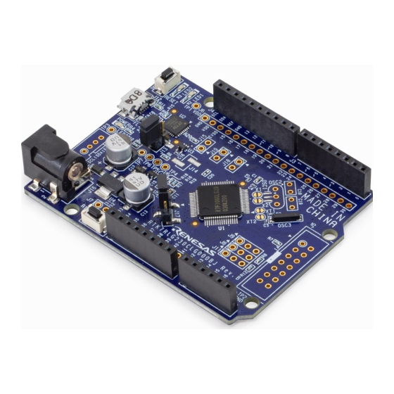
Page 10: Board Layout
RL78/G23-64p Fast Prototyping Board 2. Board Layout 2. Board Layout Figure 2-1 shows the external appearance of the top side of this product. Ten digital pins for Arduino Uno R3 User LEDs Eight digital pins for Arduino Uno R3 MCU header Reset switch J6 (15 to 30) RL78/G23 MCU... -
Page 11: Parts Layout
RL78/G23-64p Fast Prototyping Board 3. Parts Layout 3. Parts Layout Figure 3-1 shows the parts layout of this product. Figure 3-1 Parts Layout Figure 3-2 shows the external dimensions of this product. Figure 3-2 External Dimensions R20UT4814EJ0100 Rev. 1.00 Page 5 of 36 Jan.16.21... -
Page 12: Operating Environment
RL78/G23-64p Fast Prototyping Board 4. Operating Environment 4. Operating Environment Figure 4-1 shows the operating environment of this product. Install the IDE on the host PC. USB cable Host PC RL78/G23-64p Fast Prototyping Board Figure 4-1 Operating Environment R20UT4814EJ0100 Rev. 1.00 Page 6 of 36 Jan.16.21... -
Page 13: User Circuits
RL78/G23-64p Fast Prototyping Board 5.User Circuits 5. User Circuits Evaluation MCU The specifications for the power supply, system clock, and reset of the evaluation MCU (RL78/G23 with 64 pins) at the time of shipment are as follows. • Power supply: 5 V (VBUS) supplied from the USB (including the analog power supply) •... -
Page 14: Arduino Connectors
RL78/G23-64p Fast Prototyping Board 5.User Circuits Arduino Connectors The specification of the Arduino connectors is on the assumption that Arduino shields are to be connectable. However, we do not guarantee connection to all types of Arduino shield. Confirm the specifications of this product against any Arduino shield you intend to use. Figure 5-1 and Table 5-1 show the pin assignments of the Arduino... - Page 15 RL78/G23-64p Fast Prototyping Board 5.User Circuits Table 5-1 Pin Assignments of the Arduino Connectors Part No. in Name of RL78/G23 with 64 Pins the Circuit Arduino Power Port Analog Serial Others Schematics Signal* Supply J1-1 N.C. J1-2 IOREF EVDD J1-3 RESET RESET J1-4...
-
Page 16: Mcu Headers
RL78/G23-64p Fast Prototyping Board 5.User Circuits MCU Headers The MCU headers are provided as through holes; J6 includes the headers for a total of 19 pins and J7 includes the headers for a total of 16 pins. The pin headers have a pitch of 2.54 mm and the evaluation MCU is connected to the through holes for the headers. - Page 17 RL78/G23-64p Fast Prototyping Board 5.User Circuits Table 5-3 Pin Assignments of the MCU Headers (2) Part No. in Name of RL78/G23 with 64 Pins the Circuit Arduino Power Port Analog Serial Others Schematics Signal* Supply J7-34 IO31 TO02 EO17/CCD01/TI02- J7-35 IO32 TO01 EO16/CCD00/TI01/INTP5...
-
Page 18: Grove Connector
RL78/G23-64p Fast Prototyping Board 5.User Circuits Grove Connector This connector (J10) is assumed to be connected to Grove modules (through I2C). If a connector is mounted, however, connection to all Grove modules (through I2C) is not guaranteed. Use this connector after having confirmed the specifications of this product and Grove modules (through I2C) you intend to use. -
Page 19: Reset Switch
RL78/G23-64p Fast Prototyping Board 5.User Circuits Reset Switch Pressing the reset switch (SW2:RESET) applies a hardware reset to the evaluation MCU. 5.10 User Switch An optional user switch (SW1) is mounted. It is connected to pin 9 of the evaluation MCU, which operates as pin function P137. - Page 20 RL78/G23-64p Fast Prototyping Board 5.User Circuits USB-to-serial converter reset header Figure 5-3 Position of the USB-to-Serial Converter Reset Header (Top Side) R20UT4814EJ0100 Rev. 1.00 Page 14 of 36 Jan.16.21...
-
Page 21: Power-Supply Selection Header
RL78/G23-64p Fast Prototyping Board 5.User Circuits 5.13 Power-Supply Selection Header The operating power (VDD) of the evaluation MCU can be set to 5 V or 3.3 V or to supply from the emulator or external power with the use of a header (J17). Only change the jumper setting of J17 while power is not being supplied. - Page 22 RL78/G23-64p Fast Prototyping Board 5.User Circuits Power-supply selection header Figure 5-6 Setting of the Header to Select Supply from the Emulator or External Power (Top Side) R20UT4814EJ0100 Rev. 1.00 Page 16 of 36 Jan.16.21...
-
Page 23: External Power Supply
RL78/G23-64p Fast Prototyping Board 5.User Circuits 5.14 External Power Supply When the evaluation MCU is to have a desired power-supply voltage, or when more current is required, use an external power supply. The usable voltages depend on the evaluation MCU. Destinations for the connection of an external power supply: •... -
Page 24: Dc-Jack Power Supply
RL78/G23-64p Fast Prototyping Board 5.User Circuits 5.15 DC-Jack Power Supply This product can also operate with an AC adapter (7 V to 12 V) connected to the DC jack (J16). The DC jack has center-positive polarity ( ), 2.0-mm internal diameter, and 6.5-mm external diameter (type number: KLDX-SMT2-0202-ATR from KYCON). - Page 25 RL78/G23-64p Fast Prototyping Board 5.User Circuits EVDD EVDD RL78/G23 VDD_EVDD EVDD EVDD EVDD EVDD VCCIO FTDI Figure 5-9 Block Diagram of the Headers Related to Current Measurement R20UT4814EJ0100 Rev. 1.00 Page 19 of 36 Jan.16.21...
-
Page 26: Separate Pattern For Vdd And Evdd
RL78/G23-64p Fast Prototyping Board 5.User Circuits 5.17 Separate Pattern for VDD and EVDD When VDD and EVDD are to be used with different potentials, remove the given pattern for cutting (VDD_EVDD). Figure 5-10 shows the position of the pattern for cutting. Destination for the connection of an external power supply of EVDD to the source with a different potential: •... -
Page 27: Emulator Connector
This 14-pin connector (J5) is used to connect this product to an on-chip debugging E2 emulator or E2 emulator Lite, from Renesas Electronics, incorporating programming facilities (the connector is not mounted). The emulator is used for programming or debugging the evaluation MCU. -
Page 28: Handling Precautions
RL78/G23-64p Fast Prototyping Board 6. Handling Precautions 6. Handling Precautions Power to be Supplied When power is supplied to this product through the USB or DC jack, or from an emulator, note that the total current of VDD, EVDD, 5 V, and 3.3 V should not exceed the maximum current of 200 mA. Remodeling the Board Any modification of the board (including removing the patterns for cutting) shall be conducted at the user’s own responsibility. - Page 29 RL78/G23-64p Fast Prototyping Board 6. Handling Precautions Table 6-1 Power-Supply Sources and Usage Conditions Power-Supply Usage Condition Source Power supplied to Use of Use of Use of an Jumper setting the evaluation Arduino Grove emulator and shields* modules* USB* 5 V or 3.3 V Possible Possible Possible*...
- Page 30 RL78/G23-64p Fast Prototyping Board 6. Handling Precautions 3.3 V Arduino VDD/EVDD RL78/G23 7 V to 12 V 3.3 V DC jack Power-supply selection Emulator header (J17) 5 V (VBUS) Micro- Type-B External power supply VCCIO VDD/EVDD FTDI Figure 6-1 Block Diagram of the Power-Supply Circuit R20UT4814EJ0100 Rev.
-
Page 31: Developing Code
RL78/G23-64p Fast Prototyping Board 7. Developing Code 7. Developing Code Use the e studio or CS+, both of which support the evaluation MCU (RL78/G23 with 64 pins). Using the e studio Figure 7-1 shows the settings of the e studio when it is to be connected to the RL78/G23-64p Fast Prototyping Board. -
Page 32: Using Cs
RL78/G23-64p Fast Prototyping Board 7. Developing Code Using CS+ Figure 7-2 and Figure 7-3 show the settings of CS+ when it is to be connected to the RL78/G23-64p Fast Prototyping Board. • [Using Debug Tool]: Select [RL78 COM Port] from [Using Debug Tool] in the [Debug] menu. Figure 7-2 Panel for Selecting the Debug Tool •... -
Page 33: Additional Information
Copyright This document may be, wholly or partially, subject to change without notice. All rights reserved. Duplication of this document, either in whole or part is prohibited without the written permission of Renesas Electronics Europe Limited. © 2021 Renesas Electronics Corporation. All rights reserved. - Page 34 RL78/G23-64p Fast Prototyping Board User’s Manual Revision History Rev. Date Description Page Summary ⎯ 1.00 Jan.16.21 First Edition issued...
- Page 35 RL78/G23-64p Fast Prototyping Board User’s Manual Publication Date: Rev.1.00 Jan.16.21 Published by: Renesas Electronics Corporation...
- Page 36 RL78/G23 R20UT4814EJ0100...
Need help?
Do you have a question about the RL78 Series and is the answer not in the manual?
Questions and answers