Table of Contents
Advertisement
Quick Links
We have 45,000 LP502030-PCM-NTC-LD-A02554 - EEMB - Lithium Battery Rectangular 3.7V 250mAh Rechargeable in
stock now. Starting at $0.034. This EEMB part is fully warrantied and traceable.
Looking for a discount?
Check out our current promotions!
This coversheet was created by Verical, a division of Arrow Electronics, Inc. ("Verical"). The attached document was created by the part supplier,
not Verical, and is provided strictly 'as is.' Verical, its subsidiaries, affiliates, employees, and agents make no representations or warranties
regarding the attached document and disclaim any liability for the consequences of relying on the information therein. All referenced brands,
product names, service names, and trademarks are the property of their respective owners.
00000005981LF-000
R0K50110PS900BE
EOS Power
RENESAS TECHNOLOGY
Buy Now
Buy Now
Give us a call
1-855-837-4225
International: 1-555-555-5555
1-415-281-3866
1-415-281-3866
Arrow Electronics,
Arrow Electronics, Inc
Verical Division
9201 East Dry Creek Road
P.O. Box 740970
Centennial, CO 80112
Los Angeles, CA 90074-0970
Advertisement
Table of Contents

Related Manuals for Renesas RL78 Series


Summary of Contents for Renesas RL78 Series
- Page 1 We have 45,000 LP502030-PCM-NTC-LD-A02554 - EEMB - Lithium Battery Rectangular 3.7V 250mAh Rechargeable in stock now. Starting at $0.034. This EEMB part is fully warrantied and traceable. 00000005981LF-000 R0K50110PS900BE EOS Power RENESAS TECHNOLOGY Buy Now Buy Now Looking for a discount? Check out our current promotions!
- Page 2 All information contained in these materials, including products and product specifications, represents information on the product at the time of publication and is subject to change by Renesas Electronics Corporation without notice. Please review the latest information published by Renesas Electronics Corporation through various means, including the Renesas Electronics Corporation website (http://www.renesas.com).
- Page 3 Renesas Electronics products are not subject to radiation resistance design. Please be sure to implement safety measures to guard them against the possibility of physical injury, and injury or damage caused by fire in the event of the failure of a Renesas Electronics product, such as safety design for hardware and software including but not limited to redundancy, fire control and malfunction prevention, appropriate treatment for aging degradation or any other appropriate measures.
- Page 4 RSK. Renesas expressly disclaims all such warranties. Renesas or its affiliates shall in no event be liable for any loss of profit, loss of data, loss of contract, loss of business, damage to reputation or goodwill, any economic loss, any reprogramming or recall...
- Page 5 The following documents apply to the RL78/L1C Group. Make sure to refer to the latest versions of these documents. The newest versions of the documents listed may be obtained from the Renesas Electronics Web site. Document Type...
- Page 6 Electromagnetic Compatibility Liquid Crystal Display Light Emitting Diode Electromagnetic Compatibility Micro-controller Unit n/a or NA Not applicable n/c or NC Not connected Personal Computer Renesas Starter Kit Serial Array Unit Timer Array Unit UART Universal Asynchronous Receiver/Transmitter Universal Serial Bus...
-
Page 7: Table Of Contents
Table of Contents 1. Overview ..........................7 Purpose ..............................7 Features ..............................7 2. Power Supply ........................8 Requirements ............................. 8 Power-Up Behaviour ..........................8 3. Board Layout ........................9 Component Layout ............................. 9 Board Dimensions ............................ 10 Component Placement ..........................11 4. -
Page 8: Overview
Apr 04, 2014 1. Overview Purpose This RSK is an evaluation tool for Renesas microcontrollers. This manual describes the technical details of the RSK hardware. The Quick Start Guide and Tutorial Manual provide details of the software installation and debugging environment. -
Page 9: Power Supply
When the RSK is purchased, the RSK board has the ‘Release’ or stand-alone code from the example tutorial software pre-programmed into the Renesas microcontroller. On powering up the board the LCD panel will show ‘RL78’ in the bottom left and will respond to SW3 switch presses by performing an A/D conversion and displaying the result in the main part of the LCD panel. -
Page 10: Board Layout
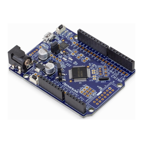
RSKRL78L1C 3. Board Layout 3. Board Layout Component Layout Figure 3-1 below shows the top component layout of the board. Application Headers Reset Switch RS232 Serial Debug LCD Power Jack connector Power LED E1 Interface RL78/L1C User LEDs User Switches Application Headers Potentiometer Figure 3-1: Board Layout... -
Page 11: Board Dimensions
RSKRL78L1C 3. Board Layout Board Dimensions Figure 3-2 below gives the board dimensions and connector positions. All the through-hole connectors are on a common 0.1 inch grid for easy interfacing. 7.0mm 3.2mm 3.00mm 13.88mm 45.00mm RL78/L1C 27.00mm 43.18mm 48.26mm 50.80mm 55.88mm 86.36mm 99.06mm... -
Page 12: Component Placement
RSKRL78L1C 3. Board Layout Component Placement Figure 3-3 below shows placement of individual components on the top-side PCB. Component types and values can be looked up using the board schematics. Figure 3-3: Top-Side Component Placement R20UT2203EG0102 Rev. 1.02 Page 11 of 37 Apr 04, 2014... -
Page 13: Connectivity
RSKRL78L1C Connectivity 4. Connectivity Internal RSK Connections The diagram below shows the RSK board components and their connectivity to the MCU. MCU Current Power Jack Draw Test Point Application Headers Micon Pin Header LCD Panel RL78/L1C E1 Debug Interface Reset RS-232 Serial Port Debug LCD USB Function Port... -
Page 14: Debugger Connections
RSKRL78L1C Connectivity Debugger Connections The diagram below shows the connections between the RSK, E1 debugger and the host PC. User Interface Cable USB Cable E1 Emulator Host PC Figure 4-2: Debugger Connection Diagram R20UT2203EG0102 Rev. 1.02 Page 13 of 37 Apr 04, 2014... -
Page 15: User Circuitry
RSKRL78L1C User Circuitry 5. User Circuitry Reset Circuit A reset control circuit is not fitted to the RSK, as the MCU is capable of voltage and power-on detection. Resets are handled internally, and the reset switch is connected directly to the RESET pin on the MCU (pin 13). -
Page 16: Leds
RSKRL78L1C User Circuitry LEDs Table There are five LEDs on the RSK. The function of each LED, its colour, and its connections are shown in Colour Function Port POWER Green Indicates the power status LED0 Green User operated LED. LED1 Orange User operated LED. -
Page 17: Lcd Panel
RSKRL78L1C User Circuitry LCD Panel A versatile LCD display panel is supplied with the RSK, and should be connected to the JA4 header. The panel is directly driven by circuitry inside the MCU. Connection information for the LCD panel is provided Table 5-4 in table below. -
Page 18: Debug Lcd Module
RSKRL78L1C User Circuitry Debug LCD Module A debug LCD header is fitted to the RSK; however the two-line debug LCD is not supplied with this kit. It is not possible to use the debug LCD and the LCD panel at the same time, and they should not both be fitted to the RSK. -
Page 19: Local Interconnect Network (Lin)
RSKRL78L1C User Circuitry Local Interconnect Network (LIN) A LIN transceiver IC is fitted to the RSK, and connected to the LIN MCU peripheral. For further details regarding the LIN protocol and supported modes of operation, please refer to the RL78/L1C hardware manual. Table 5-7 Connections between the LIN connector and the microcontroller are listed in below. -
Page 20: Configuration
RSKRL78L1C Configuration 6. Configuration Modifying the RSK This section lists the option links that are used to modify the way RSK operates in order to access different configurations. Configurations are made by modifying link resistors or headers with movable jumpers. Table 6-1 below shows the RSKRL78L1C default configuration with respect to the peripheral functionality. -
Page 21: Rs232 Serial Port Configuration
RSKRL78L1C Configuration RS232 Serial Port Configuration Table 6-2 below details the function of the option links associated with the serial port configuration. Signal Name Exclusive function Header connection SHD GND U4.20 SHDn RS232 out U4.13 SO10_TXD1 to TXD1 JA6.8 Direct Direct SO10_TXD1 RS232 in to... -
Page 22: E1 Debugger Interface
RSKRL78L1C Configuration Signal Name Exclusive function Header connection RS232 out to RS232TX U4.13 JA6.5 RS232TXD RS232 in to RS232RX U4.15 JA6.6 RS232RX Table 6-2: RS232 Serial Port Option Links (continuation) E1 Debugger Interface Table 6-3 below details the function of the option links associated with E1 Debugger configuration. The default configuration is for E1 debug/programming, but it is possible to enable Flash programming via the COM port. -
Page 23: Lcd Panel Configuration
RSKRL78L1C Configuration LCD Panel Configuration Table 6-4 below details the function of the option links associated with the LCD Panel header. Signal Name Header connection Header Port Signal Remove SEG20 JA4.31 R104 R110 SEG20_REMOOUT REMOOUT JA2.19 R110 R104 SEG23 JA4.34 R111 R114 SEG23_SCK30... -
Page 24: Iic Pin Configuration
RSKRL78L1C Configuration IIC Pin Configuration Table 6-6 below details the function of the option links associated with IIC pin configuration. Signal Name Header connection Header Port Signal Remove Board_VDD IIC Pull up Board_5V Table 6-6: IIC Option Links Power Supply Configuration Table 6-7 below details the function of the option links associated with power supply configuration. -
Page 25: Clock Circuit Configuration
RSKRL78L1C Configuration Clock Circuit Configuration Table 6-8 below details the function of the option links associated with clock circuit. Signal Name Header connection Port Connection Header Pin Remove On board X1.2 R102 R108 P121/X1 P121 External CON_X1 J1.18 R108 R102 On board X1.1 R113 R109... -
Page 26: Headers
7. Headers Application Headers This RSK is fitted with application headers, which can be used to connect compatible Renesas application devices or as easy access to MCU pins. Note that JA4 has been omitted from this list as it is the LCD panel connector, and connections are described in §5.6... - Page 27 RSKRL78L1C 7. Headers Table 7-2 below lists the connections of the application header, JA2. Application Header JA2 Header Name Header Name MCU Pin MCU Pin Circuit Net Name Circuit Net Name RESET EXTAL RESETn CON_X2 Vss1 GROUND WDT_OVF SCIaTX SO00_TXD0 IRQ0/WKUP/M1_HSIN0 SCIaRX 16/NC/NC...
- Page 28 RSKRL78L1C 7. Headers Table 7-3 below lists the connections of the application header, JA5. Application Header JA5 Header Name Header Name MCU Pin MCU Pin Circuit Net Name Circuit Net Name ADC4 ADC5 ANI16 ANI17 ADC6 ADC7 ANI18 ANI19 CAN1TX CAN1RX CAN2TX CAN2RX...
- Page 29 RSKRL78L1C 7. Headers Table 7-4 below lists the connections of the application header, JA6. Application Header JA6 Header Name Header Name MCU Pin MCU Pin Circuit Net Name Circuit Net Name DREQ DACK TEND STBYn RS232TX RS232RX RS232TX RS232RX SClbRX SClbTX SI10_RXD1 SO10_TXD1...
-
Page 30: Microcontroller Pin Headers
RSKRL78L1C 7. Headers Microcontroller Pin Headers This RSK is fitted with MCU pin headers, which are used to access all the MCU’s pins. Table 7-5 below lists the connections of the microcontroller pin header, J1. Microcontroller Pin Header J1 Circuit Net Name MCU Pin Circuit Net Name MCU Pin... - Page 31 RSKRL78L1C 7. Headers Table 7-7 below lists the connections of the microcontroller pin header, J3. Microcontroller Pin Header J3 Circuit Net Name MCU Pin Circuit Net Name MCU Pin SEG6 SEG5 SEG4_INTP6 SEG3 SEG2 SEG1 SEG0 COM3 COM2 COM1 COM0 LED1_TO06 INTP5 LED0...
-
Page 32: Code Development
8. Code Development Overview For all code debugging using Renesas software tools, the RSK board must be connected to a PC via an E1/E20 debugger. An E1 debugger is supplied with this RSK product. For further information regarding the debugging capabilities of the E1/E20 debuggers, refer to E1/E20 Emulator Additional Document for User's Manual (R20UT1994EJ). -
Page 33: Address Space
RSKRL78L1C 8. Code Development Address Space Figure 8-1 below details the address space of the MCU. This diagram is taken from the Hardware Manual Rev.1.00. The MCU fitted to the RSK has 256KB of ROM. For further details, refer to the RL78/L1C Group Hardware Manual. -
Page 34: Additional Information
Copyright This document may be, wholly or partially, subject to change without notice. All rights reserved. Duplication of this document, either in whole or part is prohibited without the written permission of Renesas Electronics Europe Limited. © 2014 Renesas Electronics Europe Limited. All rights reserved. - Page 35 REVISION HISTORY RSK RL78L1C User’s Manual Rev. Date Description Page Summary 1.00 Jan 16, 2014 First Edition issued 1.01 Mar 19, 2014 [2. List of Abbreviations and Acronyms] was updated. 15, 17 Table format of Table 5-3, 5-5, 5-6 were updated. Header pin information of Table 5-4 was fixed.
- Page 36 Renesas Starter Kit Manual: User’s Manual Publication Date: Rev. 1.02 Apr 04, 2014 Published by: Renesas Electronics Corporation...
- Page 37 SALES OFFICES Refer to "http://www.renesas.com/" for the latest and detailed information. Renesas Electronics America Inc. 2801 Scott Boulevard Santa Clara, CA 95050-2549, U.S.A. Tel: +1-408-588-6000, Fax: +1-408-588-6130 Renesas Electronics Canada Limited 1101 Nicholson Road, Newmarket, Ontario L3Y 9C3, Canada...
- Page 38 RL78/L1C Group R20UT2203EG0102...
Need help?
Do you have a question about the RL78 Series and is the answer not in the manual?
Questions and answers