Advertisement
Quick Links
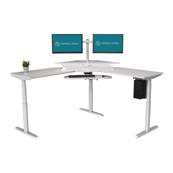
VERSA DESK
PowerLift Corner Standing Desk
®
PLCSD
REV. 09192022
How can we improve our assembly instructions?
Your comments and suggestions are important to us.
Please e-mail us at: engineering@versaproducts.com
VERSA DESK
®
American Manufacturing
®
Protected by US Patent No. 10,485,336 & 10,849,424
Assembly Instructions
Lifetime Warranty
MADE IN
AMERICA
1 (800) 465-1660
support@versadesk.com
Advertisement

Related Manuals for Versa Desk PowerLift PLCSD


Summary of Contents for Versa Desk PowerLift PLCSD
- Page 1 Assembly Instructions VERSA DESK ® PowerLift Corner Standing Desk ® PLCSD REV. 09192022 How can we improve our assembly instructions? MADE IN Your comments and suggestions are important to us. AMERICA Please e-mail us at: engineering@versaproducts.com 1 (800) 465-1660 American Manufacturing...
- Page 2 Assembly Instructions VERSA DESK ® Parts Connecting Bracket End Frame L Bracket S Bracket Mounting Tie Link Bracket Foot Control Switch Control Box Power Cord Long Cross Support 4-Piece Desktop Short Cross Support End Frame Connecting Panel 1 (800) 465-1660...
-
Page 3: Additional Tools
Assembly Instructions VERSA DESK ® Hardware 1/4-20 x 1/2” 1/4-20 x 3/4” Button 1/4-20 x 13mm Truss Head Screw Type F Screw Head Screw 1/2-13 10A x 3/4” 1/4-20 x 1/2” Button Leveler Wood Screw Head Screw P Clip Zip Tie... - Page 4 Assembly Instructions VERSA DESK ® Connect the Middle Surface to the Side Surface using (2) Link Brackets. Each Link Bracket will use (6) Wood Screws to attach to the surface. Middle Surface Side Surface Link Brackets Link Bracket Wood Screw Align the End Frame with the 4 inserts near the edge of the Side Surface.
- Page 5 Assembly Instructions VERSA DESK ® FIGURE 3-1 Depending on which size desk you ordered, you will need to follow one of the diagrams below. Please note that the cross supports labeled as long (L) will always go in between the legs that are facing each other, shown in orange.
- Page 6 Assembly Instructions VERSA DESK ® Slide the (2) Long Cross Supports into the End Frame as shown. Make sure the bigger holes on the cross supports are on the outside. Then, use (2) Type F Screws to secure the cross supports to the End Frame.
- Page 7 Assembly Instructions VERSA DESK ® Attach the remaining Side Surface to the Middle Surface using (2) Link Brackets. Once again, each Link Bracket will need (6) Wood Screws to be secured onto the surface. Middle Surface Link Bracket Wood Screw...
- Page 8 Assembly Instructions VERSA DESK ® Attach the (2) Short Cross Supports to the Connecting Bracket as shown. Once again, make sure the bigger holes are on the outside when positioning the cross supports (Refer to Step 3). You will use (2) Type F Screws to fasten these parts together as shown to the right.
- Page 9 Assembly Instructions VERSA DESK ® Attach (2) Mounting Ties to the Short Cross Supports using (4) Type F Screws as shown. Then, use (4) Wood Screws to attach the Mounting Ties to the Side Surface. Mounting Tie Short Cross Support...
- Page 10 Assembly Instructions VERSA DESK ® Attach (1) Foot to the end of each Leg as shown. Each Foot will require (4) 1/4-20 x 3/4 Button Head Screws to complete this step. 1/4-20 x 3/4 Foot Button Head Screw Twist on (2) 1/2-13 Levelers into the base of each Foot as shown.
- Page 11 Assembly Instructions VERSA DESK ® Use (2) Wood Screws to attach the Control Switch to the Side Surface as shown. The Control Switch will be placed next to the 3rd Leg as shown. Leg 2 Leg 1 Leg 3 Place Control Switch here...
- Page 12 Assembly Instructions VERSA DESK ® Connect Leg 1 to M1 on the Control Box (M1 - + blue) Connect Leg 2 to M2 on the Control Box (M2 - +blue) Connect Leg 3 to M3 on the Control Box (M3 -...
- Page 13 Assembly Instructions VERSA DESK ® Attach the End Frame L Bracket to the Middle Leg using (2) Type F Screws. Make sure the orientation of the bracket is as shown. The 3 slats should be pointing out away from the desk frame.
- Page 14 Assembly Instructions VERSA DESK ® Slide the Connecting Panel into place, align the holes with the inserts on the underside of the Middle Surface and attach with (3) Truss Head Screws. Middle Surface Truss Hd Screw Connecting Panel Attach the 4th Surface onto the brackets, align the holes of the Connecting Panel with the inserts on the underside of the surface and attach with (3) Truss Head Screws.
- Page 15 Assembly Instructions VERSA DESK ® Secure the 4th Surface with (6) Truss Head Screws going through both the End Frame L Bracket and the S Bracket as shown. 4th Surface Truss Hd Screw S Bracket End Frame L Bracket Your new desk is ready for use!
- Page 16 Assembly Instructions VERSA DESK ® Control Switch Operation Instruction Display Save Down Memory Standing Memory Sitting Position Position 1. Save Lift up/down the table to the desired height, and press button, the Display will show - while the - keeps flashing, then press button, after which, the height memory is done.
- Page 17 Assembly Instructions VERSA DESK Add-on: PowerLift Corner & Keyboard Tray Tools Parts Phillips head screw- Desk driver and/or hand drill Keyboard Tray Brackets 1/4-20 Phillips Bolt Assembly Step 1 Attach two (2) brackets to the keyboard tray assembly using four (4) 1/4-20 Phillips Bolts.
- Page 18 Assembly Instructions VERSA DESK ® Add-on: CPU holder Tools Parts Phillips head driver and/or hand drill CPU Holder Brackets 1/4-20 Phillips Bolt Lock Pin Slide Bracket Assembly Step 1 Attach the two (2) brackets to underside of the desktop with four (4) 1/4-20 Phillips Bolts, on the side of the desk you would like the CPU holder to be on.
- Page 19 Assembly Instructions VERSA DESK ® Add-on: CPU holder Assembly Step 3 Be sure that the Carriage Screws are facing the Inside of the CPU Holder and the Thumb Nuts and Washers are facing Outside. Use the Thumb Nuts to adjust the CPU Holder to the desired size.
Need help?
Do you have a question about the PowerLift PLCSD and is the answer not in the manual?
Questions and answers