
Subscribe to Our Youtube Channel
Related Manuals for Versa Desk PowerLift PLCSD


Summary of Contents for Versa Desk PowerLift PLCSD
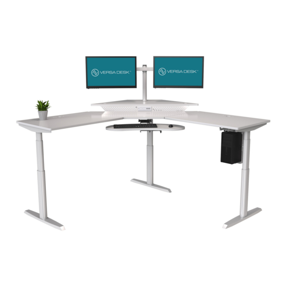
- Page 1 Assembly Instructions VERSA DESK ® PowerLift Corner Standing Desk ® REV. 05052021 PLCSD 1 (800) 465-1660 American Manufacturing Lifetime Warranty VERSA DESK ® support@versadesk.com Protected by US Patent No. 10,485,336 & 10,849,424...
- Page 2 Assembly Instructions VERSA DESK ® Tools 4mm Allen wrench Phillips head screwdriver and/or Tape measure (included) hand drill Parts Foot Side bracket Front Bracket Top frame + control box 4-Piece Desktop 3rd Leg Extension Link Bracket L Bracket S Bracket...
- Page 3 Assembly Instructions VERSA DESK ® Step 1 Slide control box (D) off the frame. Fully separate end frames (A+C), you will find the center rails (B) inside. NOTE: End frame C is placed on the side of the desk you plan to mount the control box and controller.
- Page 4 Assembly Instructions VERSA DESK ® Step 4 M6x10 Machine screw Attach end frame with L-bracket (A) to end frame with threaded-inserts (B) using (4) M6x10 machine screws. NOTE: DO NOT tighten all the way yet. Step 5 Slide the two center rails into the two end frames ensuring:...
- Page 5 Assembly Instructions VERSA DESK ® Step 7 Ensure there is no gap between surfaces and that the corners of all surfaces allign with end frame with L-bracket (Fig. A) each other by adjusting the Tighten the (4) M6x10 machine screws (Fig A.) going through end frame with L-bracket from Step 4 all the way.
- Page 6 Assembly Instructions VERSA DESK ® Step 9 M6x14 Machine screw For each leg, attach a foot with four (4) M6x14 Machine screws and tighten in a cross pattern. Step 10 Locate pre-drilled holes toward the front of the desktop. You can use the set of holes on either side, but we recommend using the right side.
- Page 7 Assembly Instructions VERSA DESK ® Step 12 Using the adhesive back, stick the Power Strip (PS) and BlueTooth App Box (BT) onto the underside of the desktop as shown below. Connect cable exiting Leg (closest to control box) directly into the control box (CB).
- Page 8 Assembly Instructions VERSA DESK ® Step 14 M6x14 Machine screws. Attach L extension bracket with two (2) M6x14 Machine screw Step 15 M6x10 Machine screws. Attach S extension bracket with two (2) M6x10 Machine screw 1 (800) 465-1660 American Manufacturing...
- Page 9 Assembly Instructions VERSA DESK ® Step 16 Slide Front Bracket into place, align the holes with the inserts on the underside of the desktop and attach with three (3) 1/4-20 Phillips Bolts. 1/4-20 Phillips Bolt Step 17 Place 4th Surface onto the brackets, align the holes of the Front Bracket woth the inserts on the underside of the surface and attach with three (3) 1/4-20 Phillips Bolts.
- Page 10 Assembly Instructions VERSA DESK ® Step 18 Secure the surface with six (6) Wood Screws going through the two brackets. 1/4-20 Phillips Bolt 1 (800) 465-1660 American Manufacturing Lifetime Warranty VERSA DESK ® support@versadesk.com Protected by US Patent No. 10,485,336 & 10,849,424...
- Page 11 Assembly Instructions VERSA DESK ® Add-on: Sit to Stand Keyboard Arm and Tray Tools Parts Phillips head screw- Desk driver and/or hand drill Keyboard Tray Brackets 1/4-20 Phillips Bolt Assembly Step 1 Attach two (2) brackets to the keyboard tray assembly using four (4) 1/4-20 Phillips Bolts.
- Page 12 Assembly Instructions VERSA DESK ® Add-on: CPU holder Tools Parts Phillips head driver and/or hand drill CPU Holder Brackets 1/4-20 Phillips Bolt Lock Pin Slide Bracket Assembly Step 1 Attach the two (2) brackets to underside of the desktop with four (4) 1/4-20 Phillips Bolts, on the side of the desk you would like the CPU holder to be on.
- Page 13 Assembly Instructions VERSA DESK ® Add-on: CPU holder Assembly Step 3 Be sure that the Carriage Screws are facing the Inside of the CPU Holder and the Thumb Nuts and Washers are facing Outside. Use the Thumb Nuts to adjust the CPU Holder to the desired size.
-
Page 14: Troubleshooting
Assembly Instructions VERSA DESK ® IMPORTANT: You must RESET the desk prior to use. Make sure no obstacles are in the desk’s path and the desktop is away from walls. Make sure all cables are the appropriate length to accomodate the change in height. -
Page 15: Technical Specifications
Assembly Instructions VERSA DESK ® Technical Specifications Height Range 23.5” - 49” (excluding desktop) Base Width 42” min. - 74” max Travel Speed 1.5” per second (no load) Weight Capacity 1000N Duty Cycle 10%. Max. 2 mins on, 18 mins off... -
Page 16: Controller Lock
Assembly Instructions VERSA DESK ® Controller Lock The keypad can be locked to prevent accidental activation or movement of the desk. To lock: Press and hold “S” button until display changes to “LOC” To unlock: Press and hold “S” button until display changes to numeric height setting.
Need help?
Do you have a question about the PowerLift PLCSD and is the answer not in the manual?
Questions and answers