Advertisement
Quick Links
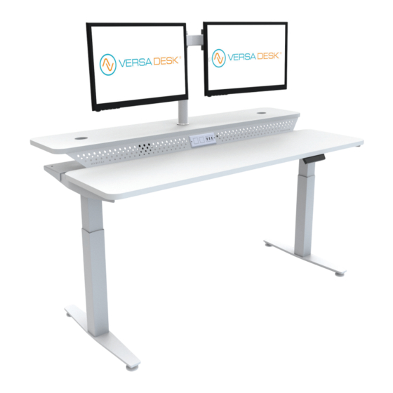
Split-Level Habitat Electric Standing Desk
SLH Series 48", 60" & 72"
SLH
MADE IN
AMERICA
14105 Avalon Boulevard, Los Angeles, CA 90061 | Tel 800-465-1660 x1 | Fax 310-353-7109
How can we improve our assembly instructions?
Your comments and suggestions are important to us.
Please e-mail us at: engineering@versaproducts.com
www.VersaDesk.com
Assembly Instructions
REV 03092022
Advertisement

Related Manuals for Versa Desk SLH Series


Summary of Contents for Versa Desk SLH Series
- Page 1 Assembly Instructions Split-Level Habitat Electric Standing Desk SLH Series 48”, 60” & 72” REV 03092022 How can we improve our assembly instructions? MADE IN Your comments and suggestions are important to us. Please e-mail us at: engineering@versaproducts.com AMERICA 14105 Avalon Boulevard, Los Angeles, CA 90061 | Tel 800-465-1660 x1 | Fax 310-353-7109...
- Page 2 Parts Top Surface (1 pc) Bottom Surface (1 pc) Back Support (1 pc) Connecting Panel (1 pc) Frame (1 pc) Leg (2 pcs) Feet (2 pcs) End Frame (2 pcs) Power Cable (1 pc) https://www.zenstores.com/help/how-con gure-zebra-gk42 Connection Cable (1 pc) Controller (1 pc) Control Unit (1 pc) Power Outlet (1 pc)
- Page 3 Hardware Handle Guide (2 pcs) Hand Screw (4 pcs) M6 x 16 (8 pcs) M6 x 12 (4 pcs) 1/4-20 x 13mm Truss Head Screw (18 pcs) M10 x 12mm 1/4-20 x 1/2 in 1/4-20 Nylon Insert Phil Pan Screw (4 pcs) 60”...
- Page 4 Assembly M6x12mm Frame End Frame Step 1 Step 2 Insert the End Frame into the Frame as illustrated above. Assemble the End Frame and Frame using (2) M6x12 bolts. Repeat for other side. Repeat for other side. Rubber Cap Bottom Surface Handle Guide Set Screw Step 3...
- Page 5 Assembly Handle Handle Step 7 Step 8 Insert (2) Handles into the Frame as illustrated above. Fix the Handle to Frame counterclockwise as illustrated above. Repeat for other side. (2 handles per side) Repeat for other side. M6 x 16 M6 x 16mm Hand Screw Step 9...
- Page 6 Assembly 11mm x 20mm Carriage Bolt Washer Back Support Connecting Panel 0.32 x 0.73 Washer Frame Frame Nylon Insert M10 x 12mm Phil Pan Head Screw Carriage Bolt 0.32 x 0.73 Nylon Insert M10x12 20 x 11 Washer Washer Step 13 Step 14 Place the Back Support on the Frame as shown.
- Page 7 Assembly Controller (HS) Leg 1 (M2) Leg 2 (M1) Note: If you are using a power supply, make sure the switch is ON before proceeding to the next step. Step 18 Step 19 Connect cable exiting Leg (closest to control box) directly into Perform Zero Setting.
- Page 8 ASSEMBLY GUIDE 5. Operating Instructions Please read below instructions carefully before operating the system. Setting Button Memory Position 1 Memory Position 2 Memory Position 3 Down 5.1 Zero Setting: When using the height adjustable frame for the first time lower the desk to the lowest height as explained below before proceeding . •...
- Page 9 ASSEMBLY GUIDE 5. Operating Instructions 5.4 Saving a desktop position: This function allows you to save a defined desktop height. One desktop height can be saved per memory position key. To save a position follow the instructions below: • Adjust the desktop to the desired desktop position you would like to save. The display will show the desktop height (e.g. 73cm). •...
- Page 10 ASSEMBLY GUIDE 6. Programmable Remote Control Operating Instructions 6.5 Changing the desktop height displayed Follow the instructions below to change the height shown on the display but not the actual position of the desktop. • Within the setting menu choose “S-5”. •...
- Page 11 ASSEMBLY GUIDE 7. Troubleshooting Control Unit or Remote Control is not working Possible Cause Remedy Ξ Power Cable is not connected Ξ Plug the power cable into the control unit Ξ Remote Control is not connected Ξ Plug in the remote control Ξ...
- Page 12 ASSEMBLY GUIDE 7. Troubleshooting Error code Note How to handle it Ξ The main supply voltage is over 45V Check the main power supply Ξ The height deviation between the screws exceeds Re-initialize Ξ Remote control connecting or communication Check the remote control cable error - -- Ξ...
- Page 13 ASSEMBLY GUIDE 7. Troubleshooting Error code Note How to handle it Ξ Motor 1 wrong direction of operation Switch the motor line or hall line Ξ Motor 1 overload Reduce load Ξ Motor 2 not connect Check the cable Ξ Motor 2 error in current sampling channel Replace the control panel Ξ...
- Page 14 ASSEMBLY GUIDE 1. General 1.1 Local value of the user manual The guiding principle for safe use and trouble-free operation of this adjustable frame is the knowledge of basic safety information and regulations. This user manual includes the most important information needed for assembling and operating the adjustable frame safely.
- Page 15 Add-on: Sit to Stand Keyboard Arm and Tray Tools Parts Phillips Head Screwdriver and/or Hand Drill Bracket A Bracket B Pan Head Screw Keyboard Tray 1/4-20 x 13mm Truss Head Screw Assembly Step 1 Attach both brackets to the keyboard assembly frame using (4) 1/4-20 x 13mm Truss Head Screws.
- Page 16 Add-on: Sit to Stand Keyboard Arm and Tray Assembly Step 2 Locate the four pre-installed inserts and align them with the mounting holes of Bracket A and Bracket B. 1/4-20 x 13mm Using (4) 1/4-20 x 13mm Truss Head Screws, Truss Head Screw attach both brackets to the underside of the desktop.
- Page 17 Add-on: CPU Holder Tools Parts Phillips Head Screwdriver Mounting Bracket Hex Head Screw CPU Holder and/or Hand Drill 1/4-20 x 13mm Truss Hd Screw Assembly Step 1 Pre-installed Insert Align the top frame of the CPU Holder with the 4 holes on the mounting Mounting bracket.
- Page 18 Add-on: CPU Holder Assembly Step 2 Decide which side you would like to place the CPU Holder on. Option Option Step 3 Align the holes of the mounting bracket with the holes on the bottom surface that you chose in Step 2. Then, use (4) 1/4-20 x 13mm Truss Head Truss Head Screws to attach the mounting bracket...
- Page 19 Add-on: CPU Holder Assembly Step 4 Bottom Frame Attach the bottom frame and the side frame of the CPU Holder to the top frame of the CPU Holder as shown. The frames are designed to simply slide into one another. Top Frame Side Frame Step 5...
- Page 20 Add-on: CPU Holder Assembly Step 6 Place your CPU into the CPU Holder. Adjust the CPU Holder to ensure that your CPU is secured properly. Look below for more details on adjustability. Adjustability d-barcode-labels/#:~:text=How%20to%20con gure%20the%20Zebra%20GK420D%20printer%20for,your%20Royal%20Mail 0barcode%20labels%20in%20Zenstores. de-labels/#:~:text=How%20to%20con gure%20the%20Zebra%20GK420D%20printer%20for,your%20Royal%20Mail%202D% 02D%20barcode%20labels%20in%20Zenstores. al-mails-2d-barcode-labels/#:~:text=How%20to%20con gure%20the%20Zebra%20GK420D%20printer%20for,your%20Roya rcode%20labels%20in%20Zenstores.
Need help?
Do you have a question about the SLH Series and is the answer not in the manual?
Questions and answers