Table of Contents
Advertisement
Advertisement
Table of Contents

Related Manuals for Shelly Wave 1 Mini


Summary of Contents for Shelly Wave 1 Mini
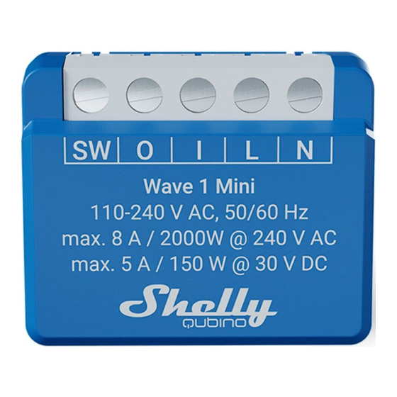
- Page 1 Wave 1 Mini Z-Wave® smart switch with potential-free contacts Extended User Guide (EN) Device: Wave 1 Mini EU Part number/Ordering Code: QMSW-0A1X8EU Z-Wave Product type ID: 0x0002 Z-Wave Product ID: 0x008E Z-Wave Manufacturer: Shelly Europe Z-Wave Manufacturer ID: 0x0460...
-
Page 2: Table Of Contents
Table of contents 1. Terminology ..........................5 2. About Shelly Qubino ........................ 5 3. About the Device ........................6 4. Electrical diagrams 110-240 V AC .................... 6 5. Installation instruction ......................7 6. About Z-Wave® ........................8 7. Z-Wave® Adding / Removing / Factory reset ................9 7.1. - Page 3 Adding / Removing menu selected ..................15 Adding / Removing menu - while pressing S- button - Add/Remove process selected ..15 Factory reset menu selected ....................15 Factory reset - while pressing S - button - Factory reset process selected ......15 Alarm Mode ..........................
- Page 4 14. Supported load types ......................26 15. Technical Specifications ......................26 16. Important disclaimer ......................27 17. Declaration of Conformity ..................... 27 18. Manufacturer ......................... 28...
-
Page 5: Terminology
1. Terminology • Device - In this document, the term “Device” is used to refer to the Shelly Qubino device that is a subject of this guide. • Gateway (GW) - A Z-Wave® gateway, also referred to as a Z-Wave® controller, Z-Wave®... -
Page 6: About The Device
3. About the Device The Device is a small form factor smart switch with potential-free contacts (dry contact). It controls the on/off function for one electrical appliance (with a load of up to 8 A AC or 5 A DC), such as a bulb, ceiling fan, IR heater, electrical lock, garage doors, irrigation system. -
Page 7: Installation Instruction
Device terminals: • N: Neutral terminal • L: Live terminal (110-240 V AC) • SW (SW1): Switch/push-button input terminal (controlling O (O1)) • O (O1): Load circuit output terminal (1) • I: Load circuit input terminal Wires: • N: Neutral wire •... -
Page 8: About Z-Wave
⚠CAUTION! Do not allow children to play with the push-buttons/switches connected to the Device. Keep the devices for remote control of Shelly Qubino (mobile phones, tablets, PCs) away from children. ⚠RECOMMENDATION: Connect the Device using solid single-core cables or stranded cables with ferrules. -
Page 9: Z-Wave® Adding / Removing / Factory Reset
7. Z-Wave® Adding / Removing / Factory reset 7.1. Adding the Device to a Z-Wave® network (inclusion) Note! All Device outputs (O, O1, O2, etc. - depending on the Device type) will turn the load 1s on/1s off /1s on/1s off if the Device is successfully added to/removed from a Z-Wave® network. Note! In case of Security 2 (S2) adding (inclusion), a dialog will appear asking you to enter the corresponding PIN Code (5 underlined digits) that are written on the Z-Wave®... -
Page 10: Adding (Inclusion) With A Switch/Push-Button
7. The green LED will be blinking in Mode 1 if the Device is successfully added to a Z-Wave® network. Note! In Setting mode, the Device has a timeout of 10s before entering again into Normal mode. 7.1.3. Adding (inclusion) with a switch/push-button 1. -
Page 11: Removing (Exclusion) With A Switch/Push-Button
7. The blue LED will be blinking in Mode 1 if the Device is successfully removed from a Z-Wave® network. Note! In Setting mode, the Device has a timeout of 10s before entering again into Normal mode. 7.2.2. Removing (exclusion) with a switch/push-button 1. -
Page 12: Z-Wave® Security 2 And Device Specific Key (Dsk)
Note! Factory reset with a switch/push-button is only possible within the first minute after the Device is connected to a power supply. 1. Connect the Device to a power supply. 2. Toggle the switch/push-button connected to any of the SW terminals (SW, SW1, SW2,…) 5 times within 3 seconds. -
Page 13: Led Signalization
The first five digits of the key are highlighted or underlined to help the user identify the PIN Code part of the DSK text. The DSK is additionally represented with a QR Code as shown on the image. Z-Wave DSK label and QR code (example) A joining node requesting to join the S2 Access Control Class or the S2 Authenticated Class will obfuscate its Public Key by setting the bytes 1…2 to zeros (0x00) before transferring its key via The DSK may be used for out-of-band (OOB) authentication. -
Page 14: Removed/Excluded
Removed/Excluded The LED will be blinking blue in Mode 1 for 30 min after every power cycle and 10 min after S button pressed. Added/Included The LED will be blinking green in Mode 1 for 30 min after every power cycle and 10 min after S button pressed. -
Page 15: Adding / Removing Menu Selected
Adding / Removing menu selected When the menu is selected the LED will be on blue, for maximum of 10 seconds. Adding / Removing menu - while pressing S- button - Add/Remove process selected When the menu is executing the LED will be blinking blue in Mode 3. Factory reset menu selected When the menu is selected the LED will be on red, for maximum of 10 seconds. -
Page 16: Parameter No. 17 - Restore The O (O1) State After A Power Failure
Default value: 2 Values & descriptions: • 0 - momentary switch (push button), • 1 - toggle switch (contact closed - ON / contact opened - OFF), • 2 - toggle switch (Device changes status when switch changes status) Parameter No. 17 - Restore the O (O1) state after a power failure This parameter determines if the on/off status is saved and restored for the load connected to O (O1) after a power failure. -
Page 17: Parameter No. 23 - O (O1) Contact Type - No/Nc
Values size: 2 Byte Default value: 0 Values & their descriptions: • 0 - Auto ON Disabled • 1 - 32535 = 1 - 32535 seconds or milliseconds – see Parameter no. 25. Set timer units to s or ms for O (O1) resolution 100ms Parameter No. -
Page 18: Parameter No. 91 - Water Alarm
Values & descriptions: • 0 – timer set in seconds • 1 – timer set in milliseconds Parameter No. 91 - Water Alarm This parameter determines how the device should respond to the reports of alarm frames. The parameters consist of 4 bytes, the three most significant bytes are set according to the official Z-Wave protocol specification. -
Page 19: Parameter No. 93 - Co Alarm
• NOTIFICATION_EVENT_SMOKE_ALARM_SMOKE_DETECTED 0x01 • NOTIFICATION_EVENT_SMOKE_ALARM_SMOKE_DETECTED_UNKNOWN_LOCATION 0x02 Values size: 4 Byte Default value: 0 Values & descriptions: • 0 no action • 1 open relay • 2 close relay Parameter No. 93 - CO Alarm This parameter determines how the device should respond to the reports of alarm frames. The parameters consist of 4 bytes, the three most significant bytes are set according to the official Z-Wave protocol specification. -
Page 20: Parameter No. 105 - Led Signalisation Intensity
This parameter determines how the device should respond to the reports of alarm frames. The parameters consist of 4 bytes, the three most significant bytes are set according to the official Z-Wave protocol specification. The notification types it reacts to are as followed: Notification Type: •... -
Page 21: Parameter No. 201 - Serial Number 1
The parameter is Advanced and may be hidden under the Advanced tag. Values size: 1 Byte Default value: 0 Values & descriptions: 0 - No action 1 - Factory reset After reset is performed, the parameter value is automatically set to 0. Parameter No. -
Page 22: Parameter No. 203 - Serial Number 3
0x00000000 - 0x7FFFFFFF Parameter No. 203 - Serial Number 3 This parameter contains a part of device’s serial number. The parameter is Read-Only and cannot be changed. The parameter is Advanced and may be hidden under the Advanced tag. Values size: 4 Byte Default value: Device specific Values &... -
Page 23: Z-Wave Notifications Command Class
Supporting Command Class Basic COMMAND_CLASS_BASIC is mapped into COMMAND_CLASS_SWITCH_BINARY, for enabling Switch (O) control: Switch (O) will be turned ON or OFF, after receiving the BASIC_SET command: Basic Command received Mapped Command (binary Switch) Basic Set (0xFF) Switch Binary Switch (0xFF) Basic Set (0x00) Switch Binary Switch (0x00) Basic GET... - Page 24 Action to restore - press any switch-push button connected to any SW (SW, SW1, SW2, …) terminal...
-
Page 25: Z-Wave Associations
Z-Wave Associations Associations are used for direct communication between the Device and other devices within your Z-Wave network without the need of the Z-Wave gateway. Max. number of associated devices per group is 9. This value is fixed and cannot be configured. Each association group supports the association of up to 9 devices (nodes). -
Page 26: Supported Load Types
• SWITCH_MULTILEVEL_START_LEVEL_CHANGE : initiate a transition to a new level (increase or decrease light intensity in case of dimmer, or move shutter up or down, …) • SWITCH_MULTILEVEL_STOP_LEVEL_CHANGE : stop an ongoing transition (stop increase or decrease light intensity in case of dimmer, or stop moving shutter up or down, …) Supported load types •... -
Page 27: Important Disclaimer
Hereby, Shelly Europe Ltd. (former Allterco Robotics EOOD) declares that the radio equipment type Wave 1 Mini is in compliance with Directive 2014/53/ EU, 2014/35/EU, 2014/30/EU, 2011/65/EU. The full text of the EU declaration of conformity is available at the following internet address: https://shelly.link/Wave1Mini-DoC... -
Page 28: Manufacturer
Manufacturer Shelly Europe Ltd. (former Allterco Robotics EOOD) Address: 103 Cherni vrah Blvd., 1407 Sofia, Bulgaria Tel.: +359 2 988 7435 E-mail: zwave-shelly@shelly.cloud Support: https://support.shelly.cloud/ Web: https://www.shelly.com Changes in the contact data are published by the Manufacturer at the official website:...
Need help?
Do you have a question about the Wave 1 Mini and is the answer not in the manual?
Questions and answers