Advertisement
Quick Links
MV-821-IP Quick Setup Guide
4)
Initial Unit Configuration
For configuration of the MV-821-IP Multiviewer (for the internal 'Multiviewer' block and the four 'Video IP Input circuit'
blocks), please refer to the MV-821 User Manual located on the
The MV-821 User Manual also describes the following for the MV-821-IP:
•
Architecture.
•
Front and rear connectors and controls; Hardware Installation.
•
RollCall templates for internal 'Multiviewer' block and 'Video IP Input circuit' blocks.
•
Getting started.
•
Specification.
5) Edit Video Wall Layout and Configure Alarms (with Orbit)
Grass Valley web site
See the
for Orbit and MV-821 user
manuals. Perform the following steps to check basic
functionality for the video wall, setting an alarm, and Orbit
network connection:
Pull the default layout from the Multiviewer:
1. Run Orbit on a PC.
(Orbit v2.1 or later)
2. File > New Project.
Click "Connected
Multiviewer Project".
Browse to a PC folder
where wall layout data will be stored. Folder must be
empty. Click Next.
3. Select a multiviewer unit from displayed list. Click
Choose. (Remember to select RollCall Domain ID)
4. Username admin,
Password admin.
5. Click Login.
The video wall layout is pulled
from unit and read into Orbit.
The Orbit Project Screen:
6. Click the Walls icon. Click Wall1 in drop-down list.
The Wall
Editor
screen is
shown for
Wall1.
Make a visible change to the wall:
7. Click on a middle wall tile, to select it.
Tile Properties are shown on the right.
MV-821-IP Multiviewer Quick Setup Guide
Issue 1 Rev 1
RMY3 MV-821-IPQSG
Grass Valley web
site.
8. Change Property Tile Type to Analogue Clock.
The selected Orbit tile changes to a round clock face.
9. Click File > Save File to save this change.
Enable a Video Input Lost alarm:
10. Click Multiviewer > Input Alarms.
A dialog is shown with tabs. On the:
• Input Tab - Set Selected Input to Input 1.
• Alarm Tab - Scroll down Selected Alarm box.
Select Video Input Lost. Select Alarm Enable.
• Input Tab - Click Copy All.
11. Click OK. Click File > Save File to save change.
Video Input Lost alarm is enabled on multiviewer inputs.
Push the modified project to the multiviewer:
12. Click Project > Select Multiviewer.
Enter the IP address (MV Control port) of the
MV-821-IP.
13. Click Project > Push.
The MV-821-IP adopts the new wall layout and an
analogue clock is shown.
Provoking a 'Video Input Lost' alarm warning:
14. Disconnect Video Input 1 at router input (source).
Video loss is detected.
A slow-flashing,
red rectangular
border
appears around the
corresponding video wall tile.
The alarm may also be seen in a separate Orbit window:
15. Expand the Network View Pane MV-821-IP item
and right-click on the Input 1 item.
A Details text window shows Input 1 status.
status message appears when
Red text
a Video Input Loss alarm is triggered.
www.grassvalley.com
Page 3
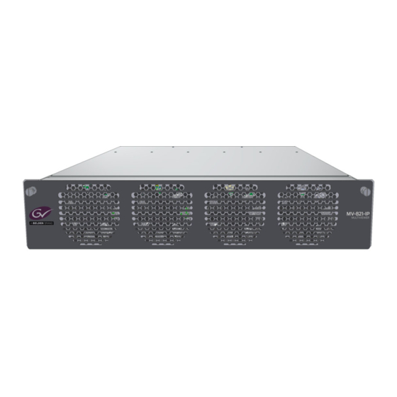
MV-821-IP
Standalone Multiviewer
Flexible Multi-head Displays
Quick Setup Guide
Thank you for purchasing a new MV-821-IP Multiviewer.
This Quick Setup Guide will help you get running as quickly as possible.
Upon Receipt of your MV-821-IP Multiviewer:
• The product is supplied in dedicated packaging provided by Grass Valley;
it should not be accepted if delivered in inferior or unauthorized materials.
• Unpack the MV-821-IP product carefully and check components against the packing list.
If anything is incorrect, please notify your Grass Valley Partner or notify Grass Valley directly.
• Check all components have not been damaged in transit.
If any damage has occurred, notify your Grass Valley Partner (or Grass Valley directly) and the carrier
immediately. Have your order details ready.
• Retain the original packing materials. They could be useful for future transporting or shipping.
Safety Information:
Caution: MV-821-IP Multiviewer products should only be
serviced by qualified personnel.
Caution: Take anti-static precautions when handling the
product, or when inserting or removing any modules.
Caution: Ensure the MV-821-IP Multiviewer front door is
properly closed at all times.
Caution: The MV-821-IP can be equipped with optical
outputs, which contain low-power laser beams.
Warning: Do not look into an optical output. Laser
radiation can cause irreversible and permanent damage of
eyesight.
Warning: Do not look at the end of a fiber to see if light is
coming out. Use optical instrumentation.
Warning: Unused optical outputs should be covered, to
prevent direct exposure to the laser beam.
Warning: To reduce the risk of electric shock, do not
expose this equipment to water or moisture.
www.grassvalley.com
Advertisement

Subscribe to Our Youtube Channel
Related Manuals for Belden grass valley MV-821-IP


Summary of Contents for Belden grass valley MV-821-IP
- Page 1 MV-821-IP Quick Setup Guide Initial Unit Configuration MV-821-IP For configuration of the MV-821-IP Multiviewer (for the internal ‘Multiviewer’ block and the four ‘Video IP Input circuit’ Grass Valley web site. blocks), please refer to the MV-821 User Manual located on the The MV-821 User Manual also describes the following for the MV-821-IP: Standalone Multiviewer •...
- Page 2 MV-821-IP Quick Setup Guide MV-821-IP Quick Setup Guide 2) Connections 1) Fitting the MV-821-IP Multiviewer into a 19” Equipment Rack The MV-821-IP is designed to be installed and used Rear connectors etc. are shown in Figure 5. Rear Air Exhaust holes Air Flow Out in a standard 483mm (19 inch) equipment rack.
Need help?
Do you have a question about the grass valley MV-821-IP and is the answer not in the manual?
Questions and answers