Advertisement
Quick Links
Have this manual in the palm of
yout hand through the FG Finder
app.
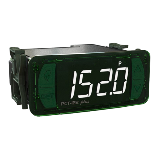
1. DESCRIPTION
The PCT-122 plus is a dedicated pressure switch for condensing units with features that contribute to the
energy efficiency of the refrigeration system. It has two analog outputs that allow precise control of the suction
and discharge processes, allowing the activation of frequency inverters, electronic fans, control module for
compressor capacity variable solenoid (varistep). It also has three relay outputs for ON-OFF compressor or
fan control.
It has two inputs for pressure sensors and temperature sensors, allowing monitoring of low and high
pressures, in addition to superheating and subcooling measurements.
Using its integrated clock, it automatically activates the economical setpoint and night mode. The digital inputs
enable remote commands for various purposes, such as: turning off the control, alarms, economical mode,
night mode, among others. The PCT-122 plus allows you to configure the RS-485 communication port for
the MODBUS-RTU protocol. For more information about the implemented commands and the registration
table, contact Full Gauge Controls.
2. SAFETY RECOMMENDATIONS
- Make sure you know the correct way to install the controller;
- Make sure that the power supply is turned off and that it is not going to turn on during the installation of the
controller;
- Read this manual before installing and using the controller;
- Use appropriate Personal Protective Equipment (PPE);
- Where it will be used in areas subject to splashing water, such as refrigerated counters, install the protective
film that comes with the controller;
- The installation procedures must be carried out by a competent engineer, respecting current regulations.
3. APPLICATIONS
- Condenser units, Suction/discharge control in refrigeration systems, Superheating and subcooling
monitoring.
4. TECHNICAL SPECIFICATIONS
Power Source
Average consumption
Pressure control range
Pressure sensor input
Pressure resolution
Temperature sensor /
Digital Input
Temperature control range
Temperature resolution
Operating temperature
Working humidity
Clock (RTC)
Analog outputs
Capacity of outputs
OUT1, OUT2 e OUT3
Degree of protection
Maximum dimensions
Bay size
5. DISPLAY AND KEYS
LED indicator control ON/OFF
LED indicator Fan enabled
LED indicator Compressor
Enabled
Flatec Key
Set Key
plus
PCT-122
6. INSTALLATION - PANEL AND ELECTRICAL CONNECTION
71
± 0,5
mm
Size of the Bay for
inserting the device
Panel (Front View)
CAUTION
WHERE THE INSTALLATION LOCATION NEEDS TO BE SEALED AGAINST LIQUIDS, THE OPENING IN WHICH THE CONTROLLER IS
TO BE INSTALLED MUST BE NO MORE THAN 70.5x29mm. THE SIDE CLASPS MUST BE SECURED IN SUCH A WAY AS TO CREATE A
TIGHT RUBBER SEAL THAT PREVENTS ANY LIQUIDS ENTERING THE OPENING AND THE CONTROLLER.
PCT-122 plus
DIGITAL PRESSURE CONTROLLER AND INDICATOR
Suction
Discharge
Function
Switch off
Modbus
Control
Control
Lock
Control
Protocol
Functions
24Vdc ± 10%
-14,5 a 3191 PSI / -1 a 220,0 BAR
(operating range of the configurable sensor)
(*) P1 and P2: 4 - 20mA
0,1 PSI / 0,1 BAR
(*) T1, T2, T3 and T4: Temperature Sensor
(SB19, SB41, SB59 and SB70)
These inputs can be configured
individually as digital inputs
-50 to 105°C / -58 to 221°F
0,1°C / 0,1°F
-20 to 60°C / -4 to 140°F
10 to 90% RH (without condensation)
Energy backup: CR1220 battery
Time keeping of up to 10 years
Accuracy:
±6 minutes/year
AN1 and AN2: 10Vcc
(± 1%)10mA máx.
240 Vac, 1/8 HP
120 Vac, 1/10 HP
120-240Vac, 5A Resistive
120-240Vac 5W General Use
IP 65 (front)
76 x 34 x 94mm / 2,99" x 1,33" x 3,70" (WxHxD)
X = 71
±0,5mm(2,79"±0,02") Y= 29±
0,5(1,14" 0,02")
(see Image 5)
(*) Sensors sold separately
LED indicator temperature unit
LED indicator (pressure unit: psi/bar)
P B
Up Key
Down Key
Panel
(Side View)
IP 65
FRONT
Programming
Quick
Monitoring
Degree
in Series
System
of Protection
Coupling
Connection
7. CONNECTION DIAGRAM
T1
T2
11
12
13
14
15
1
2
3
4
5
Source
24Vdc
P1
T1, T2, T3 and T4 - Configurable between
Temperature sensor and digital input;
P1 - Suction pressure transducer
P2 - Discharge pressure transducer
7.1. Condenser unit configuration
The configuration of parameter [,F03] ''Condenser unit configuration'' allows you to choose how the
control outputs will act depending on the type of condenser used.
450 mA
* The Control Module can be a frequency inverter or a motor module with analog input for speed control.
INDEX
SUCTION
1
Variable
2
Variable
Variable
3
Variable
4
Variable + 1x On/Off
5
Variable + 1x On/Off
6
Variable + 1x On/Off
7
1x On/Off
8
9
1x On/Off
10
2x On/Off
11
1x On/Off
12
2x On/Off
NEW CONNECTION SYSTEM (QUICK CONNECTION):
PUSH-IN WIRE CONNECTORS - QUICKLY
±
PUSH-IN Connection:
- Hold the wire close to its end and insert it into the
required opening.
- If necessary, press the button to help make the
connection.
- Ferrule type terminals can be used.
- For the signal connections, the ferrule must be at
least 12mm.
In the power connectors the pin must be at least
7mm.
NOTES 1 - Signal Connectors:
- Connections 1 to 20 must use wire of a gauge
between 0.2 and 1,5mm² (26 and 16AWG).
NOTES 2 - Power Connectors:
- Connections 21 to 25 must use wire of a gauge
between 0.2 and 2.5mm² (26 and 12AWG).
7.2. Connecting the temperature sensors
- Connect the wires of the T1 Sensor to terminals ''11 and 12'', the wires of the T2 sensor to terminals and
''13 and 14'', the wires of the T3 sensor to terminals ''15 and 16'' and the wires of the T4 sensor to
terminals ''17 and 18'': the polarity is indifferent.
- The length of the sensor cables can be increased by the user themselves up to 200 meters (650 ft.),
using a 2x24 AWG PP cable.
7.3. Recommendations from NBR5410 and IEC60364 standards
a) Install surge protectors to the controller's power supply.
b) Install transient suppressors - suppressor filter (type RC) - in the circuit to increase the working life of
the controller's relay.
c) The sensor cables can be together, but not in the same conduit as the power supply fot the controller or
the loads.
T3
T4
SITRAD
A B
16
17
18 19
20
21 22 23
6
7
8 9 10
OUT1
P2
VARIABLE
VARIABLE
COMPRESSOR
FAN
CONTROL
CONTROL
AN1 - VARIABLE COMPRESSOR CONTROL
AN2 - VARIABLE FAN CONTROL
OUT1, OUT2 e OUT3 - Relay Outputs,
Control defined according to parameterization
SUCTION
StSc
Start command (Control Module)*
AnSc
R1Sc
R2Sc
DISCHARGE
StDs
Start command (Control Module)*
AnDs
R1Ds
R2Ds
DISCHARGE
AN1
AN2
1x On/Off
AnSc
-
2x On/Off
AnSc
-
Variável
AnSc
AnDs
Variable + 1x On/Off
AnSc
AnDs
1x On/Off
AnSc
-
Variable
AnSc
AnDs
Variável + 1x On/Off
AnSc
AnDs
1x On/Off
-
-
2x On/Off
-
-
1x On/Off
-
-
Variable
-
AnDs
Variable
-
AnDs
TO DISCONNECT THE PUSH-IN:
- To disconnect the wire, press the button and
remove it
evolution
23 24 25
OUT2
OUT3
Power Supply
of loads
OUT2 and OUT3
Power Supply
of load
OUT1
Analog output 0-10V
Relay 1 - On/Off
Relay 2 - On/Off
Analog output 0-10V
Relay 1 - On/Off
Relay 2 - On/Off
OUT1
OUT2
OUT3
StSc
R1Ds
-
StSc
R1Ds
R2Ds
StSc
StDs
-
StSc
StDs
R1Ds
StSc
R1Sc
R1Ds
StSc
R1Sc
StDs
StSc
R1Sc
R1Ds
R1Sc
R1Ds
-
R1Sc
R1Ds
R2Ds
R1Ds
R1Sc
R2Sc
StDs
R1Sc
-
StDs
R1Sc
R2Sc
The wire must be stripped
Ferrule Terminal
Advertisement

Related Manuals for Full Gauge Controls PCT-122 plus


Summary of Contents for Full Gauge Controls PCT-122 plus
- Page 1 1. DESCRIPTION 7. CONNECTION DIAGRAM The PCT-122 plus is a dedicated pressure switch for condensing units with features that contribute to the SITRAD energy efficiency of the refrigeration system. It has two analog outputs that allow precise control of the suction and discharge processes, allowing the activation of frequency inverters, electronic fans, control module for compressor capacity variable solenoid (varistep).
-
Page 2: Installation Procedure
Brief press: View date and time. b) Remove the side clasps (Diagram 6 - Item 16): to do this, press on the elliptical central part (with the Full Gauge Controls Logo) and slide the clasps back; Brief press: inhibit sound alarm. - Page 3 9.3.10 Turn Off Control Functions 9.3.8 View mesurements The temporary display mode can be activated through the access menu using option [MEAS] or by Turning off the control functions allows the controller to be used as a temperature / pressure indicator only, >...
- Page 4 CELSIUS (°C) / PSI FAHRENHEIT (°F) / BAR Description Unit Standard Unit Standard [,F42] Discharge temperature fan hysteresis ON/OFF (digital outputs) 20,0 °C 10,0 36,0 °F 18,0 [,F43] Discharge temperature variable fan hysteresis (analog output) 20,0 °C 10,0 36,0 °F 18,0 [,F44] Minimum discharge temperature setpoint...
- Page 5 F20 - Maximum critical pressure tolerance time – temperature control: 9.5.1 Description of the parameters Time that the suction pressure must remain below the value configured in [,F19] for the compressors to turn off. F01 - Control delay when energizing the product: When the instrument is turned on, it can remain disabled for a while, delaying the start of the process.
- Page 6 F46 - Integral time (Reserved): F69 - Low superheat alarm: Parameter not available in this model. F70 - High superheat alarm: Minimum and maximum limits for superheat alarms. F47 - Minimum time between activations: Note: Superheat alarms only validate with a compressor running. Fixed hysteresis of 1ºC/1°F. Minimum time between two activations of digital outputs during discharge.
- Page 7 F99 - Operating mode of the digital input 1: F115 – Function Lock Mode: F100 - Operating mode of the digital input 2: Allows and configures function lock (see item 9.3.9). F101 - Operating mode of the digital input 3: [,,,0] - Does not allow function locking.
-
Page 8: Discharge Controls
10. SUCTION CONTROL 11. DISCHARGE CONTROLS 10.1 Suction control associated with a VCC-analog compressor 11.1 Discharge control associated with a fan with inverter modulation With [,f03] set to 1,2,3 or 4, suction is controlled only by a VCC-Analog compressor. In these options, the digital output OUT1 is used to control the Start of the VCC compressor. - Page 9 12. WARNINGS / ALARMS / ERRORS Description: T3 sensor low temperature alarm. Effect: Case [,F05] - Suction operating mode = Temperature sensor T3: turns off [ALt3] 12.1 Warnings suction compressors, disregarding the time between deactivations. Pressure in P1 transducer (suction) [P-1,] Otherwise: indicative alarm.
-
Page 10: Warranty
01 (one) year from accredited retailers, starting from the consignment date on the sales invoice. After this year, the Extended Panel warranty will continue to be honored for purchases from retailers if the device is sent directly to Full Gauge Controls. This Full Gauge Controls extended panel allows controllers to be installed in Evolution and Ri lines, whose period is valid in Brazil.
Need help?
Do you have a question about the PCT-122 plus and is the answer not in the manual?
Questions and answers