Advertisement
Quick Links
Wired Systems
Preassembled DIN Rail
Cabinets (UL)
Failure to comply with these instructions may result in serious injury (including death) and property damage.
Risk of Fire, Electrical Shock, Cuts, or other Casualty Hazards - Installation and maintenance of this product must be performed by a
qualifi ed electrician. This product must be installed in accordance with the applicable installation code by a person familiar with the
construction and operation of the product and hazards involved. For continued protection against shock hazard replace all covers
and guards after fi eld wiring is completed.
Safe work practices - Before installing or performing any service, the power MUST be turned OFF at the branch circuit breaker.
According to NEC 240.83(D), if the branch is used as the main switch for a lighting circuit, the circuit breaker should be marked with
"SWD". All installations should be in compliance with the National Electrical Code and all state and local codes.
Risk of Fire and Electric Shock - Make certain power is OFF before starting installation or attempting any maintenance. Disconnect
power at fuse or circuit breaker. Dynalite load controllers may contain circuits from more than one power source.
Risk of Burn - Disconnect power and allow fi xture to cool before handling or servicing.
Risk of Personal Injury - Due to sharp edges, handle with care. Always use at least two people when lifting and mounting heavy or
large units.
DISCLAIMER OF LIABILITY: Signify and its subsidiaries assumes no liability for damages or losses of any kind that may arise from the improper,
careless, or negligent installation, handling or use of this product.
IMPORTANT: Read carefully before installing devices and fi xtures. Retain for future reference.
NOTICE: Do not use this equipment for other than the intended use.
NOTICE: Specifi cations and dimensions subject to change without notice.
ATTENTION Receiving Department: Note actual device descriptions and any shortage or noticeable damage on delivery receipt. File claim
for common carrier (LTL) directly with carrier. Claims for concealed damage must be fi led within 15 days of delivery. All damaged material,
complete with original packing must be retained.
NOTICE: If a room is wired for two circuits using two separate hot leads, it is very important to connect only one circuit per relay. Both circuits
must be fed from the same phase.
NOTICE: Ensure that all devices are fi rmly seated on the DIN rails before beginning fi eld wiring. To remount a device simply pull the black
tab(s) away from the DIN rail, push down on the side of the device with the tab and allow the tabs to snap back into place.
NOTICE: Caution, 0-10 V and DALI wires may not be SELV/Class 2 (UL) and should never be considered touch safe. Basic insulation or higher is
required between 0-10 V/DALI wires and mains cabling.
NOTICE: Ensure that the supply is fully isolated at an external breaker before opening doors. Test that power has been removed before
starting to handle conductors.
NOTICE: Ensure that high voltage and low voltage wiring remains separate.
NOTICE: All new wiring must be fully verifi ed before applying power.
NOTICE: Output ratings vary for diff erent load types. Check individual device compliance and ratings before installation.
IMPORTANT SAFEGUARDS
≤90%
Installation Instructions
Cabinet part codes:
DRC1220FR-GL-ENC
DRPC1602-ENC
DRC2420FR-GL-ENC
DFPC802-ENC
DBC1220-GL-ENC
DFPC1602-ENC
DBC2420-GL-ENC
DMPC802-ENC
DBC516FR-ENC
DMPC1602-ENC
DBC120-DALI-ENC
DNG485-ENC
DBC320-DALI-ENC
PDEG-ENC
DRPC802-ENC
PDEG-S-ENC
www.dynalite.com
Advertisement

Related Manuals for Philips dynalite DRC1220FR-GL-ENC


Summary of Contents for Philips dynalite DRC1220FR-GL-ENC
- Page 1 Installation Instructions Cabinet part codes: DRC1220FR-GL-ENC DRPC1602-ENC DRC2420FR-GL-ENC DFPC802-ENC Wired Systems DBC1220-GL-ENC DFPC1602-ENC DBC2420-GL-ENC DMPC802-ENC DBC516FR-ENC DMPC1602-ENC Preassembled DIN Rail DBC120-DALI-ENC DNG485-ENC Cabinets (UL) DBC320-DALI-ENC PDEG-ENC DRPC802-ENC PDEG-S-ENC IMPORTANT SAFEGUARDS Failure to comply with these instructions may result in serious injury (including death) and property damage. Risk of Fire, Electrical Shock, Cuts, or other Casualty Hazards - Installation and maintenance of this product must be performed by a qualifi ed electrician.
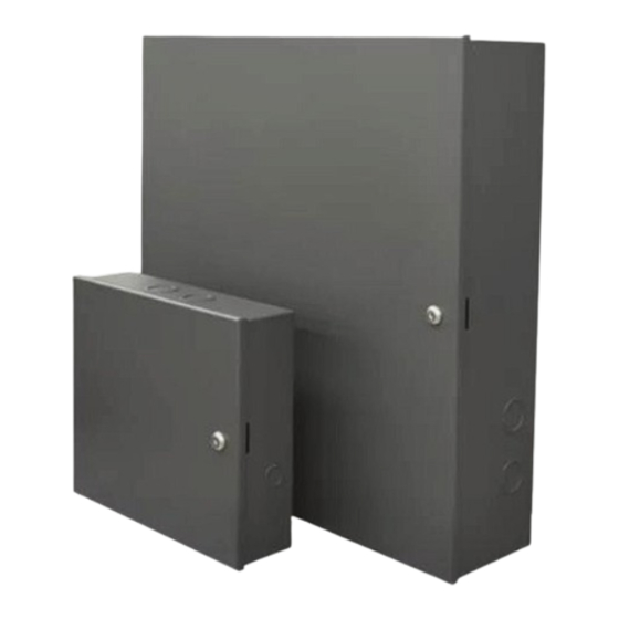
- Page 2 Overview – please read The Philips Dynalite DIN Rail Cabinets (panels) consist of an enclosure • Remove packaging material and discard before beginning field with premounted interior DIN rail devices. The panels are designed, wiring. built, and tested to strict safety regulations. By following the •...
- Page 3 DIN rail cabinets (UL) Cabinet part code Cabinet type Included Devices Output Description Derated Total Box Load DRC1220FR-GL-ENC ULC 1 DDRC1220FR-GL 12 x 20 Amp Relay Outputs 130 Amps 130 Amps DRC2420FR-GL-ENC ULC 1 2 x DDRC1220FR-GL 24 x 20 Amp Relay Outputs per DDRC1220FR-GL 12 x 1-10 V/DALI Broadcast Outputs DBC1220-GL-ENC...
-
Page 4: Mounting The Enclosure
• Locating cabinets away from heat generating equipment will Mounting Considerations benefit long term reliability of all devices. • The cabinets are designed for surface mounting. Consult Philips Dynalite support for flush mounting options. • Use suitable conduits and couplers to link the raceways to the controller chassis. - Page 5 Run the wiring Connecting DALI loads All cabinets have been designed to provide a clear layout and logical progression for all power circuits. Field wiring for branch circuits that On controllers named with the -DALI suffi x, the two wire DALI are connected to the dimmers and relay controllers, enter from the addressable bus may be connected to (Sensor and Dry Contact) input sides of the cabinet.
- Page 6 Wiring flow Internal wiring example – AC powered devices AC input (provided by installer) 6 A fuse AC input AC input AC input Device A Device B Device C RS-485 DyNet To external devices Internal wiring example – DC powered devices AC input (provided by installer) 6 A fuse AC to DC PSU...
-
Page 7: Device Wiring
Device wiring DINGUS-UI- DINGUS-DUS- RJ45-DUAL RJ45-DUAL Antumbra Revolution Contactor* 30° / 90° Sensor (277-347 V) 360° Sensor *Not supplied by Signify Relay Controller DDRC1220FR-GL Output Ratings/Channel (CH) Load Type CH1-CH12 General Use 16 A, 277 V (UL) 20 A, 240 V (CE) Incandescent ≤... - Page 8 Device wiring eed, 0/1-10 V / DALI Controllers 10+ AWG DDBC1200 100-240 V 5.5 Lb-in 0.5 A 0.6 Nm ≤ 5 mm Control Channel Ratings ≤ 80/CH ≤ 300 DALI CH10 CH11 CH12 Broad- Guaranteed 160 mA cast Maximum 250 mA SUPPLY: 100-240V ~ 50/60Hz 0.5A max.
- Page 9 Device wiring DALI-2 Controllers DDBC120-DALI x10-16 Output Ratings/Channel (CH) Control Channel Ratings Load Type 16 A, 277 V (UL) DUS… DPMI… Electronic Driver 20 A, 240 V (CE) ≤ 64/CH DALI DALI Inrush Current 500 A Address- Guaranteed 220 mA able Maximum 250 mA x34-64...
- Page 10 Device wiring Modular Controllers DDMC802 100-240 V 10+ AWG 16 A 5.5 Lb-in 0.6 Nm ≤ 5 mm DGTM402 4 x 2 A Reverse-phase • • dimmer module SUPPLY DA+ DA- DA+ DA- DA+ DA- DA+ DA- DA+ DA- DA+ DA- DA+ DA- WARNING: MANUAL OVERRIDES DO NOT PROVIDE PERMANENT ISOLATION DDMC802...
- Page 11 Device wiring Gateways DDNG485 4EE5 DDNG485 SERVICE SWITCH: 1 PUSH = NETWORK ID PUSH & HOLD FOR 4 SEC = RESET RS-485 GATEWAY SERVICE LED SIGNAL MODES: SUPPLY: Port 1: Input 12-24V , 380mA max, SELV / Class 2 (UL) OK, NETWORK BUSY Port 1 Port 2...
- Page 12 Device wiring Gateways PDDEG-S 100-277 V Copper conductors only, 75°C rated minimum SUPPLY BACnet gateway Supply terminals: 0.6 Nm (5.5 in-lb) max. tightening torque 0.25 A PDDEG-S Ethernet Gateway - Supervisor 4EE5 SERVICE SWITCH: SUPPLY: 100-277V~ 50/60Hz 0.25A 1 Push = DyNet sign on 4 Sec Press = Soft Reset DyNet: 12V 0.3A...
- Page 13 Lighting control network topologies PDEG-S-ENC Other panels Ethernet PDEG-S-ENC Other panels Trunk RS-485 DyNet Ethernet DNG485-ENC Trunk RS-485 DyNet Port 1 Port 2 DNG485-ENC RS-485 DyNet RS-485 DMX512 Port 1 Port 2 RS-485 DyNet RS-485 DMX512 DNG485-ENC DNG485-ENC RS-485 DyNet - up to 800m Port 1 Port 2 Port 1...
- Page 14 No representation or warranty as to the accuracy or completeness of the information included herein is given and any liability for any action in reliance thereon is disclaimed. Philips and the Philips Shield www.dynalite.com Emblem are registered trademarks of Koninklijke Philips N.V. All other trademarks are owned by Signify Holding or their respective owners.
Need help?
Do you have a question about the dynalite DRC1220FR-GL-ENC and is the answer not in the manual?
Questions and answers