Advertisement
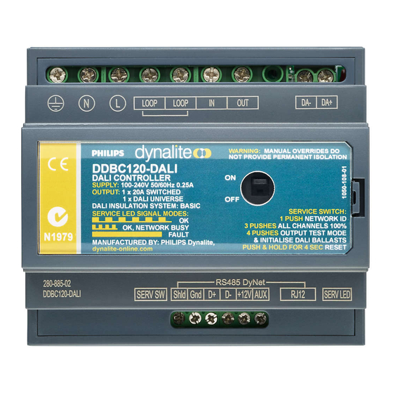
DDBC120-DALI
DALI Multi Master Controller
Installation Manual
features
Supply – 100-240V 50/60Hz Single Phase at 0.25A.
1 x DALI Output – Suitable for DALI HF ballasts, electronic low-
voltage transformers and LED fixtures. Philips Dynalite multi
master enabled for use with DPMI940-DALI and DUS804C-DALI
only.
1 x Feed Thru Switched Circuit – rated at 20A
Built-in DALI Bus Power Supply of 220mA @ 16VDC – No
external DALI power supply required.
Override and Status Indicator for Switched Channel
Dry Contact Interface – Can be programmed to perform many
different functions. The factory settings will cause this input to
transmit network identification information.
Many Control Options – Control of this device can be via a
combination of methods eg. Serial control port, relay contacts,
push button control panels, infrared receivers, timeclocks and
Philips Dynalite user interfaces on the DALI network.
Simple Installation – DIN Rail mount facilitates installation.
All connection terminals accessible without disassembly.
electrical diagram
Warning – This is a class A product. In a domestic environment this product may
cause radio interference, in which case the user may be required to take adequate
measures.
Special Programming – This device is designed for professional installation only,
and will only operate in basic modes unless programmed via a computer.
programming is required, contact your local agent for details. Once the data cable is
connected to the devices, the factory default settings will allow any control panel to
control all channels in all dimmers.
Check Connections – Re-tighten all connections after installation.
Power Sources – This device should only be operated from the type of supply
specified on the front cover. This device must be earthed.
Output Circuit – The load on the switched circuits should not exceed the specified
capacity of 20A, these circuits should be fed via a 20A circuit breaker.
Load Control Circuit – A 2 core DALI bus cable is required to be run to the loads,
this cable is in addition to the mains feed.
Load Type – This product is intended to control DALI devices and Switched
devices.
Mounting Location – Install in a dry, well-ventilated location. Controllers may emit
some mechanical noise. Take this into account when deciding the mounting location.
Data Cable – Use screened, stranded RS485 data cable with three twisted pairs.
Segregate from mains cable by 300mm minimum. Connect devices in a 'daisy
chain'. A data cable connected to an energized device is live. Do not cut or terminate
live data cables.
WARNING:
Do not connect any DALI terminals
or wires to mains power. DALI wires are NOT
SELV and should never be considered touch
safe. Basic insulation or higher is required
between DALI wires and mains cabling.
Do not connect external DALI power supply to
the same DALI bus.
To reduce the risk of fire or electric shock, do
not expose this device to rain or moisture. Do
not energise unless the front cover is in place.
The device must be earthed.
Installation,
programming and maintenance must be carried
out by qualified personnel.
If
Advertisement
Table of Contents

Related Manuals for Philips dynalite DDBC120-DALI


Summary of Contents for Philips dynalite DDBC120-DALI
- Page 1 1 x DALI Output – Suitable for DALI HF ballasts, electronic low- cause radio interference, in which case the user may be required to take adequate voltage transformers and LED fixtures. Philips Dynalite multi measures. master enabled for use with DPMI940-DALI and DUS804C-DALI Special Programming –...
- Page 2 DDBC120-DALI Instruction Manual Rev B.doc. Specifications subject to change without notice. Philips Dynalite manufactured by WMGD Pty Ltd (ABN 33 097 246 921) Unit 6, 691 Gardeners Road Mascot NSW 2020 Australia Tel: +61 2 8338 9899 Fax: +61 2 8338 9333 Email dynalite.info@philips.com...
Need help?
Do you have a question about the dynalite DDBC120-DALI and is the answer not in the manual?
Questions and answers