
Related Manuals for Philips Dynalite DMC2


Summary of Contents for Philips Dynalite DMC2
-
Page 1: Dmc2
Area for main photograph Area for insert photo W: 46.1mm up to 79 mm H: 46.1mm X: 12.6mm absolute on page Y: 132.6mm abs on page This insert has a shadow DMC2 Installation Guide Revision 03... -
Page 3: Table Of Contents
Contents DMC2 Product Overview DMC2 Enclosure 1.1.1 Dimensions 1.1.2 Enclosure diagram DSM2-XX 1.2.1 Dimensions / Diagrams DMD31X Module 1.3.1 Dimensions 1.3.2 DMD31X module output wiring DMP310-GL 1.4.1 Dimensions / Diagrams DMR310 / DMR316 1.5.1 Dimensions / Diagrams Installation Installation requirements Cabling Mounting the DMC2 Inserting and connecting modules... - Page 4 Dynalite products for use by registered owners. Some information may become superseded through changes to the law and as a result of evolving technology and industry practices. Any reference to non- Philips Dynalite products or web links does not constitute an endorsement of those products or services.
-
Page 5: Product Overview
Product Overview The Philips Dynalite DMC2 is a versatile modular controller that consists of a power supply module, communication module, and up to two interchangeable control modules. The power and communication modules are listed below: • DSM2-XX – Single-phase or three-phase supply module that supplies power to the communications and control modules. -
Page 6: Dmc2 Enclosure
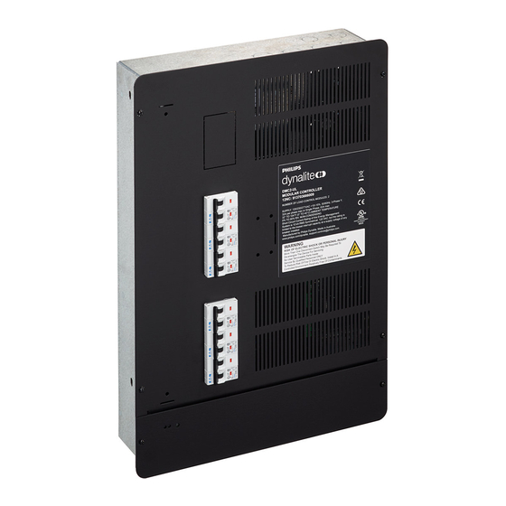
January 15, 2019 DMC2 Enclosure The DMC2 enclosure is a galvanized steel case with powder coated front covers. It includes mounting bays for power supply module, communication module and two output modules. 1.1.1 Dimensions DMC2 Product Overview... -
Page 7: Enclosure Diagram
January 15, 2019 1.1.2 Enclosure diagram DMC2 Product Overview... -
Page 8: Dsm2-Xx
January 15, 2019 DSM2-XX The DSM2-XX fits into the top module bay of the enclosure, and supplies power to the communication and control modules. 1.2.1 Dimensions / Diagrams DMC2 Product Overview... -
Page 9: Dmd31X Module
January 15, 2019 DMD31X Module The DMD31X module is a three-channel signal controller. Each channel is individually configurable to DALI Broadcast, 1-10V or DSI. 1.3.1 Dimensions DMC2 Product Overview... -
Page 10: Dmd31X Module Output Wiring
January 15, 2019 1.3.2 DMD31X module output wiring The control signal must be terminated into the top six terminals on the module. The power circuit must be terminated into the bottom six terminals as indicated in the diagram below. Ensure that each signal and power channel has been paired and segregated correctly. For installation involving 120 VAC circuits only: Wire all output circuits using conductors suitable for Class 1 / Light and Power circuits rated 150 V minimum. -
Page 11: Dmp310-Gl
January 15, 2019 DMP310-GL The DMP310-GL is a phase-cut dimming controller, software-selectable between leading edge and trailing edge, and is compatible with most dimmable drivers. 1.4.1 Dimensions / Diagrams DMC2 Product Overview... -
Page 12: Dmr310 / Dmr316
January 15, 2019 DMR31X The DMR31X module is a three-channel relay controller, capable of controlling most types of switched loads, including lighting and motor control. 1.5.1 Dimensions / Diagrams DMC2 Installation... -
Page 13: Installation
Once assembled, powered and terminated correctly, this device will operate in basic mode. A new Philips Dynalite user interface on the same network will turn all output lighting channels on from button 1 and off from button 4 allowing testing of network cables and terminations. -
Page 14: Installation Requirements
January 15, 2019 Installation requirements The DMC2 is designed for indoor use only. If installed in an outdoor location, the DMC2 must be housed in a suitable well-ventilated enclosure. Choose a dry location that will be accessible after the installation is complete. To ensure sufficient cooling, you must mount the DMC2 vertically, as shown below. -
Page 15: Cabling
January 15, 2019 Cabling Remove the required knockout plates for the supply cables before mounting the enclosure. The DMC2 includes the following cabling knockouts. Cables should enter the enclosure through the nearest knockout to the relevant module. Supply/Control: Top: 4 x 28.2mm (1.1”) 2 x 22.2mm (0.87”) Side: 7 x 28.2 (1.1”) -
Page 16: Mounting The Dmc2
January 15, 2019 Mounting the DMC2 The DMC2 can be surface or recess mounted. Surface mounting uses four mounting points, indicated below: Recess mounting is supported by four mounting holes suitable for M6 (1/4”) fasteners, two on either side of the enclosure as shown below. The minimum spacing between studs is 380mm (15”), and the minimum mounting depth is 103mm (4.1”). -
Page 17: Inserting And Connecting Modules
January 15, 2019 Inserting and connecting modules Control modules fit in either mounting bay, and you can install any two modules in the same unit. Control modules are connected to the supply module with the supplied wiring loom, and to the communication bus with the ribbon cable connectors on the left-hand side of the enclosure. - Page 18 January 15, 2019 5. Connect the supplied wiring loom to the modules. Use only the loom supplied with the unit, and do not modify the loom in any way. Refer to 2.4.4 Wiring loom. 6. Check and retighten all terminals. Remove the required knockouts from the top cover plate, then reattach the cover plate to the unit and make sure all screws are tightened securely.
-
Page 19: Dcm-Dynet
January 15, 2019 2.5.1 Communication Module - DCM-DyNet The DCM-DyNet module is mounted in the bottom section of the enclosure, below the high-voltage barrier. Remove the protective film from the keypad before installing this module. Insert the DCM-DyNet: 1. Adjust the jumper located next to the control ribbon cable connector to select the required DyNet voltage: 12V (factory default) or 24V. -
Page 20: Dsm2-Xx
January 15, 2019 2.5.2 Supply Module - DSM2-XX The DSM2-XX module is mounted in the top section of the enclosure. Insert the DSM2-XX: 1. Connect the 24VDC Class 2/SELV supply plug to the two-way socket behind the DMC communication bus socket. Note that the internal power supply is derived from phase L1. - Page 21 January 15, 2019 4. Terminate the supply wires into the right-hand side of the terminals and to the Earth bar on the right-hand side of the enclosure. 5. Terminate the supply group of the wiring loom into the left-hand side of the terminals. Refer to 2.4.4 Wiring loom for more information.
-
Page 22: Control Module Installation
January 15, 2019 2.5.3 Control module installation Control Modules can be mounted in any available module location within the DMC unit. Insert the control module: 1. Mount the circuit breakers. Use only the circuit breakers provided in the installation kit, oriented so that they are isolated when switched toward the output side as shown. - Page 23 January 15, 2019 5. Terminate the control module’s supply input wires into the right side of the circuit breakers. 6. Terminate the corresponding Module group of the wiring loom into the left side of the circuit breakers. 7. Recheck all terminal screws and tighten. The control module installation is now complete.
-
Page 24: Wiring Loom
January 15, 2019 2.5.4 Wiring loom The DMC wiring loom is designed to ensure correct wiring from the power supply module to the control modules. The terminations for each module are held in the required order with clearly labelled plastic brackets. Make sure the labels on each bracket correspond to the wiring on each module, as shown here. -
Page 25: Post-Installation Testing
January 15, 2019 Post-installation testing If you need to energize the load circuits on the DMC before connecting it to the rest of the network, you can replace the cover and energize the device immediately. The default factory programming sets all channels to 100% output. For more information on testing and troubleshooting procedures, visit https://dynalite.org/ Service LEDs and switch... -
Page 26: Manual Override Keypad
January 15, 2019 Manual override keypad WARNING: Manual overrides do not provide permanent isolation. Isolate at the supply before performing work on load circuits. Once the DMC2 has been fully installed and energized, you can remove the bottom cover plate and use the keypad on the DCM-DyNet module to test each module and channel in the device. - Page 28 DMC2 Post-installation testing Philips and the Philips Shield Emblem are registered trademarks of Koninklijke Philips N.V. All other trademarks are owned by Signify Holding or their respective owners.
Need help?
Do you have a question about the Dynalite DMC2 and is the answer not in the manual?
Questions and answers