Table of Contents

Related Manuals for DBI SALA ExoFit NEX X300


Summary of Contents for DBI SALA ExoFit NEX X300
- Page 1 User Manual of Product 1: 3M 1113130 DBI-SALA ExoFit X300 Comfort Construction Positioning Safety Harness, Construction Fall Protection, Aluminum Back and Hip D-Rings, Auto-Locking Quick Connect Leg and Chest Buckles, X-Large...
- Page 2 ExoFit NEX™ Full Body Harness Model Numbers: (See back pages.) USER INSTRUCTION MANUAL EXOFIT NEX™ FULL BODY HARNESS This manual is intended to meet the Manufacturer’s Instructions as required by ANSI Z359 and CSA 259.10 and should be used as part of an employee training program as required by OSHA WARNING: This product is part of a personal fall arrest, restraint, work positioning, climbing, controlled descent, or rescue system.
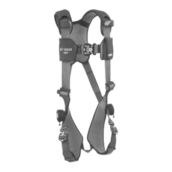
- Page 3 Figure 1 - ExoFit NEX™ Vest Style Full Body Harness A. Shoulder Strap w/Hybrid Padding B. Duo-Lok™ Quick Connect Buckle C. Chest Strap D. Hybrid Chest Pad with i-Safe™ RFID Tag & Labels E. Revolver™ Torso Adjustor F. Tech-Lite™ Side D-Ring G. Leg Strap H. Tech-Lite™ Dorsal D-Ring I. Trauma Strap Figure 2 - ExoFit NEX™...
- Page 4 1.0 APPLICATION PURPOSE: The DBI-SALA ExoFit NEX™ Full Body Harness (Figure 1 and Figure 2) should be used as a component ™ in personal fall arrest, restraint, work positioning, climbing, controlled descent, or rescue systems (see Table 1). ExoFit NEX™ Harnesses included in this manual are full body harnesses and meet ANSI Z359.1, OSHA, and CSA Z259.10 requirements.
- Page 5 Figure 3 - Applications Fall Arrest Restraint Ladder Climbing Work Positioning Work Positioning or Controlled Descent, with Seat Sling Work Positioning, with Seat Sling Work Positioning, with Seat Sling - Tower Climbing Anchorage Anchorage Connector Connecting Subsystem (SRL shown) D Full Body Harness Restraint Lanyard Backup Fall Arrest System...
- Page 6 Figure 4 - Fall Clearance (Lanyards) Figure 5 - Swing Falls RD = LL + DD + HH + C Required Fall Clearance Distance Length of Lanyard (Specifi ed on labeling) Deceleration Distance = 4 ft (1.2 m) except: • for ANSI/OSHA Lanyards with Free Fall greater than 6 ft (1.8 m) up to 12 ft (3.7 m), or user weights greater than 310 lbs (141 kg) up to 420 lbs (191 kg);...
-
Page 7: Other Restrictions
MAKING CONNECTIONS: Use only self-locking snap hooks and carabiners with this equipment. Only use connectors that are suitable to each application. Ensure all connections are compatible in size, shape and strength. Do not use equipment that is not compatible. Ensure all connectors are fully closed and locked. DBI-SALA connectors (snap hooks and carabiners) are designed to be used only as specifi... - Page 8 2.10 CONNECTING SUBSYSTEMS: Connecting subsystems (self-retracting lifeline, lanyard, rope grab and lifeline, cable sleeve) must be suitable for your application (see Table 1). See subsystem manufacturer’s instructions for more information. Some harness models have web loop connection points. Do not use snap hooks to connect to web loops.
- Page 9 3.0 DONNING AND USE WARNING: Do not alter or intentionally misuse this equipment. Consult Capital Safety when using this equipment in combination with components or subsystems other than those described in this manual. Some subsystem and component combinations may interfere with the operation of this equipment. Use caution when using this equipment around moving machinery, electrical and chemical hazards, and sharp edges.
- Page 10 EXOFIT NEX™ VEST STYLE FULL BODY HARNESS: The ExoFit NEX™ Vest Style Harness incorporates loops for a removable waist belt (see Figure 9). The belt can be installed through the two loops in the harness located in the lower back shoulder straps. The belt will pass through the harness just below the padded area.
- Page 11 Figure 11 - Donning the ExoFit NEX™ Vest Style Full Body Harness Step 1 Step 2 Step 3 Duo-Lok™ Quick Connect Buckles Connection: Connect buckle ends by inserting the tab into the receptor until a click is heard. Strap Adjustment: Rotate Webbing Lock to unlocked position .
- Page 12 EXOFIT NEX™ CROSS-OVER STYLE FULL BODY HARNESS: The ExoFit NEX™ Cross-Over Style Harness incorporates loops for a removable waist belt. The belt can be installed through the two loops in the harness located in the lower back shoulder straps (see Figure 10). The belt will pass through the harness just below the padded area.
- Page 13 Figure 12 - Donning the ExoFit NEX™ Cross-Over Style Full Body Harness Step 1 Step 2 Step 3 Duo-Lok™ Quick Connect Buckles Connection: Connect buckle ends by inserting the tab into the receptor until a click is heard. Strap Adjustment: Rotate Webbing Lock to unlocked position .
- Page 14 SUSPENSION TRAUMA STRAP: The Figure 13 - Suspension Trauma Straps ExoFit NEX™ Full Body Harness is equipped with a Suspension Trauma Strap (Figure 13) to help prolong allowable suspension time in the event of a fall from height. It should only be used in situations where a fall has occurred or for training.
- Page 15 4.0 TRAINING It is the responsibility of the purchaser and the user of this equipment to assure that they understand these instructions and are trained in the correct care and use of this equipment. They must also be aware of the operating characteristics, application limits, and the consequences of improper use of this equipment.
-
Page 16: Maintenance, Servicing, And Storage
Step 5. Record inspection data: Record the inspection date and results in the Inspection and Maintenance Log (see Section 9). Step 6. Inspect the Stitched Impact Indicator: The stitched impact indicator is a section of webbing that is lapped back on itself and secured with a specifi c stitch pattern holding the lap (see Figure 16). -
Page 17: Specifications
7.0 SPECIFICATIONS PERFORMANCE: • Maximum Free Fall Distance: No greater than 6 ft (1.8 m), per federal law and ANSI Z359.1. NOTE: Harness is acceptable for use with free fall distances exceeding 6 feet (1.8 m) if used with appropriate connecting system. •... - Page 18 8.0 LABELING The following labels must be securely attached and fully legible: All Models ANSI Models CSA Models...
- Page 19 ANSI Models CSA Models Vest Style Harness Cross-Over Style Harness...
-
Page 20: Inspection And Maintenance Log
9.0 INSPECTION AND MAINTENANCE LOG SERIAL NUMBER: MODEL NUMBER: DATE PURCHASED: DATE OF FIRST USE: INSPECTION DATE INSPECTION ITEMS CORRECTIVE ACTION MAINTENANCE NOTED PERFORMED Approved By: Approved By: Approved By: Approved By: Approved By: Approved By: Approved By: Approved By: Approved By: Approved By: Approved By:... - Page 21 INSPECTION AND MAINTENANCE LOG SERIAL NUMBER: MODEL NUMBER: DATE PURCHASED: DATE OF FIRST USE: INSPECTION DATE INSPECTION ITEMS CORRECTIVE ACTION MAINTENANCE NOTED PERFORMED Approved By: Approved By: Approved By: Approved By: Approved By: Approved By: Approved By: Approved By: Approved By: Approved By: Approved By: Approved By:...
- Page 22 INSPECTION AND MAINTENANCE LOG SERIAL NUMBER: MODEL NUMBER: DATE PURCHASED: DATE OF FIRST USE: INSPECTION DATE INSPECTION ITEMS CORRECTIVE ACTION MAINTENANCE NOTED PERFORMED Approved By: Approved By: Approved By: Approved By: Approved By: Approved By: Approved By: Approved By: Approved By: Approved By: Approved By: Approved By:...
- Page 23 ANSI Models 1100381 1113014 1113090 1113191 1113281 1113361 1113426 1113517 1113586 1113655 1100382 1113014H 1113091 1113191H 1113282 1113362 1113427 1113518 1113587 1113656 1100383 1113015 1113092 1113192 1113285 1113363 1113428 1113519 1113588 1113657 1100384 1113016 1113093 1113192H 1113286 1113364 1113434 1113520 1113589 1113658 1100385...
- Page 24 CSA Models 1103070C 1113060C 1113136C 1113217 1113326C 1113455 1113566C 1113614C 1113681C 1122224C 1103071C 1113061C 1113139C 1113218 1113327C 1113456 1113567C 1113615C 1113682C 1123121C 1103072C 1113061CH 1113142C 1113219 1113328C 1113457 1113568C 1113616C 1113683C 1123122C 1103073C 1113064C 1113145C 1113220C 1113329C 1113458 1113569C 1113617C 1113684C 1123123C 1103074C...
-
Page 25: Limited Lifetime Warranty
LIMITED LIFETIME WARRANTY Warranty to End User: D B Industries, Inc., dba CAPITAL SAFETY USA (“CAPITAL SAFETY”) warrants to the original end user (“End User”) that its products are free from defects in materials and workmanship under normal use and service. This warranty extends for the lifetime of the product from the date the product is purchased by the End User, in new and unused condition, from a CAPITAL SAFETY authorized distributor.
Need help?
Do you have a question about the ExoFit NEX X300 and is the answer not in the manual?
Questions and answers