Table of Contents
Advertisement
Quick Links
The Ultimate in Fall Protection
Nano-Lok Edge
Form No: 5903543
rev: C
INSTRUCTION MANUAL
ANSI Z359.14 Class B
This manual is intended to meet the Manufacturer's
Instructions as required by ANSI Z359.14 and should
be used as part of an employee training program as
required by OSHA.
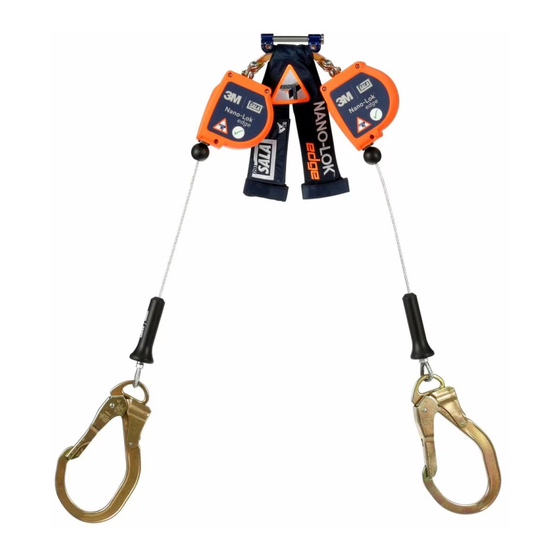
Figure 1 – Nano-Lok™ Edge Self Retracting Lanyard Models
Nano-Lok Edge WrapBax
ANSI A10.32
SELF RETRACTINg LANyARdS
Model
3500210
3500211
3500212
3500214
3500215
3500216
3500247
3500248
WrapBax
3500213
3500225
3500226
3500227
3500229
3500230
3500231
3500249
3500246
WrapBax
3500228
model Numbers: (See Figure 1)
Connectors - Lanyard End
1
1
1
1
1
1
1
2
2
2
2
2
2
2
© Copyright 2013, Capital Safety
1
1
2
2
Advertisement
Table of Contents

Related Manuals for DBI SALA Nano-Lok Edge Series


Summary of Contents for DBI SALA Nano-Lok Edge Series
- Page 1 INSTRUCTION MANUAL ANSI Z359.14 Class B ANSI A10.32 SELF RETRACTINg LANyARdS This manual is intended to meet the Manufacturer’s Instructions as required by ANSI Z359.14 and should model Numbers: (See Figure 1) The Ultimate in Fall Protection be used as part of an employee training program as required by OSHA.
- Page 2 WARNING: This product is part of a personal fall arrest, work positioning, or rescue system. The user must follow the manufacturer’s instructions for each component of the system. These instructions must be provided to the user of this equipment. The user must read and understand these instructions before using this equipment. Manufacturer’s instructions must be followed for proper use and maintenance of this equipment.
- Page 3 1.0 APPLIcATIONs PURPOSE: DBI/SALA Nano-Lok edge™ Self retracting Lanyards with leading edge capability (SrL-Les) are designed for use in applications where falls may occur, including falls over edges, such as roofing, leading edge construction, etc. SrL-Les are designed to be a component in a personal fall arrest system (PFAS). Figure 1 illustrates the SrL-Les covered by this manual.
- Page 4 FREE FALL: When anchored overhead, SrL-Les will limit the free fall distance to 2 ft. (61 cm) or less. To avoid increased fall distances, anchor the SrL-Le directly above the work level. Avoid working where your lifeline may cross or tangle with that of another worker.
- Page 5 Figure 5 – Fall Clearance Figure 5A: User Total Weight up to 220 lbs (100 kg). 6 ft (1.8 m) WrapBax Clearance required Configuration (1.8) (1.5) (1.2) (1.2) (1.5) (1.8) (2.4) (2.1) (0.9) (0.6) (0.3) (0.3) (0.6) (0.9) (2.1) (2.4) in feet (meters) See Figure 5A between working...
- Page 6 Figure 5 – Fall Clearance Figure 5C: User Total Weight up to 420 lbs (191 kg) 8 ft (2.4 m) Clearance required WrapBax (2.4) (1.8) (1.5) (1.2) (1.2) (1.5) (1.8) (2.1) (0.9) (0.6) (0.3) (0.3) (0.6) (0.9) (2.1) (2.4) in feet (meters) Configuration 10 ft (3.0 m) between working...
- Page 7 Figure 6 – Fall Clearance - WrapBax Snap Hook to Anchor, Straight Connection Figure 6A: User Total Weight up to 220 lbs (100 kg). 6 ft (1.8 m) 8 ft (2.4 m) Clearance required WrapBax (2.7) (2.4) (2.1) (1.8) (1.5) (1.2) (0.9) (0.9)
- Page 8 Figure 6 – Fall Clearance - WrapBax Snap Hook to Anchor, Straight Connection Figure 6C: User Total Weight up to 420 lbs .(191 kg) 8 ft (3.0 m) 10 ft (2.4 m) Clearance (2.7) (1.8) (1.5) (1.2) (1.2) (1.5) (1.8) (2.7) (2.4) (2.1)
- Page 9 2.14 COMPATIBILITy OF COMPONENTS: Unless otherwise noted, Capital Safety equipment is designed for use with Capital Safety approved components and subsystems only. Substitutions or replacements made with non approved components or subsystems may jeopardize compatibility of equipment and may affect safety and reliability of the complete system. IMPORTANT: Read and follow manufacturer’s instructions for associated components and subsystems in your personal fall arrest system.
- Page 10 3.0 INsTALLATION PLANNINg: Plan your fall protection system before starting your work. Account for all factors that may affect your safety before, during, and after a fall. Consider all requirements and limitations defined in Section 2. HARNESS MOUNTINg: Nano-Lok edge SrL-Les include an interface for mounting on a Full Body Harness just below the Dorsal D-ring.
- Page 11 Figure 9 – Single SRL-LE Harness Interface Step 1 Step 2 Step 3 Step 4 A - Shoulder Straps B - Dorsal D-ring C - Locking Buttons d - Locking Pin E - Harness Interface F - Hook and Loop Straps g - red Band on Locking Pin...
- Page 12 4.0 use WARNING: Do not alter or intentionally misuse this equipment. Consult Capital Safety when using this equipment in combination with components or subsystems other than those described in this manual. Some subsystem and component combinations may interfere with the operation of this equipment. Use caution when using this equipment around moving machinery, electrical hazards, chemical hazards, sharp edges, or overhead materials that may fall onto the lifeline.
- Page 13 Figure 10 – Nano-Lok SRL-LE System Connections Figure 10A: Figure 10B: Figure 10C: Figure 10d: A - Anchorage Point B - Snap Hook C - SrL-Le Harness Interface d - rebar Hook E - WrapBax Hook Locking mechanism F - WrapBax Hook Gate Latch g - WrapBax Anchorage TWIN LEg NANO-LOK EdgE SRL-LEs: With the twin leg Nano-Lok edge SrL-Les mounted on the back of a Full Body Harness, the user can have continuous fall protection (100 % tie-off) while ascending, descending, or moving laterally (see Figure 10B).
- Page 14 i-Safe™ RFID TAG: The Nano-Lok Edge SRL-LE Figure 11 – i-Safe RFID Tag includes an i-Safe™ Radio Frequency Identification (RFID) tag. (See Figure 11) The RFID tag can be used in conjunction with the i-Safe handheld reading device to simplify inspection and inventory control and provide records for your fall protection equipment.
- Page 15 MATERIALS: Material specifications for the Nano-Lok SRL-LE are as follows: Housing: Super Tough Nylon, UV Resistant Motor Spring: Stainless Steel drum: Aluminum Alloy Swivel: Zinc Plated Steel Fasteners: Zinc Plated Alloy Steel Screws; Lifeline: 3/16” 7 X 19 Galvanized Cable Stainless Steel rivets Wrapbax Web: Kevlar/Dyneema...
- Page 16 Figure 12 – SRL-LE Labeling Specifications/Inspection Label Inspection Label Anchorage and Use Label...
- Page 17 Table 1 - Nano-Lok Edge™ Self Retracting Lanyards Inspection Schedule and Checklist Inspection Frequency Type of Use Application Examples Conditions of Use Competent Person Infrequent to Light Rescue and Confined Good Storage Conditions, Indoor Annually Space, Factory or Infrequent Outdoor Use, Room maintenance Temperature, Clean environments moderate to Heavy...
- Page 18 Figure 13 – SRL-LE Inspection Figure 14 – Cable Lifeline Kinked Wire rope Broken Wires Bird-Caging Welding Splatter Figure 15 – WrapBax Webbing Frayed Heavily Soiled Welding Burns...
- Page 19 APPeNdIx A - NANO-LOk edGe sRL-Le Web LOOP HARNess AdAPTeR The Nano-Lok edge SrL-Le Web Loop Harness Adapter (P/N 3500046) (see Figure A) is a web loop that allows the SrL-Le to be used on harnesses that are not compatible with the SrL-Le Harness Interface connector (see Figure 2.) This applies primarily to harnesses with fixed D-Rings that do no have enough slack in the harness web to allow the pin of the connector to pass through.
- Page 20 APPeNdIx A - NANO-LOk edGe sRL-Le ATTAcHMeNT sTRAP Nano-Lok Edge SRL-LE Attachment Strap (P/N 3100184) Figure g (See Figure G) The Attachment Strap has hook ends (7) and loop ends (8). Figure H STEP 1: (See Figure H) Position Attachment Strap hook ends (7) under harness shoulder straps and loop ends (8) over energy absorber covers as shown.
- Page 21 INSPECTION ANd MAINTENANCE LOg SERIAL NUMBER: MOdEL NUMBER: dATE PURCHASEd: dATE OF FIRST USE: INSPECTION dATE INSPECTION ITEMS CORRECTIvE ACTION MAINTENANCE NOTEd PERFORMEd Approved By: Approved By: Approved By: Approved By: Approved By: Approved By: Approved By: Approved By: Approved By: Approved By: Approved By: Approved By:...
- Page 22 INSPECTION ANd MAINTENANCE LOg SERIAL NUMBER: MOdEL NUMBER: dATE PURCHASEd: dATE OF FIRST USE: INSPECTION dATE INSPECTION ITEMS CORRECTIvE ACTION MAINTENANCE NOTEd PERFORMEd Approved By: Approved By: Approved By: Approved By: Approved By: Approved By: Approved By: Approved By: Approved By: Approved By: Approved By: Approved By:...
- Page 24 LIMITEd LIFETIME WARRANTy Warranty to End User: D B Industries, Inc., dba CAPITAL SAFETY USA (“CAPITAL SAFETY”) warrants to the original end user (“End User”) that its products are free from defects in materials and workmanship under normal use and service. This warranty extends for the lifetime of the product from the date the product is purchased by the End User, in new and unused condition, from a CAPITAL SAFETY authorized distributor.
Need help?
Do you have a question about the Nano-Lok Edge Series and is the answer not in the manual?
Questions and answers