Table of Contents
Advertisement
Quick Links
User's Manual
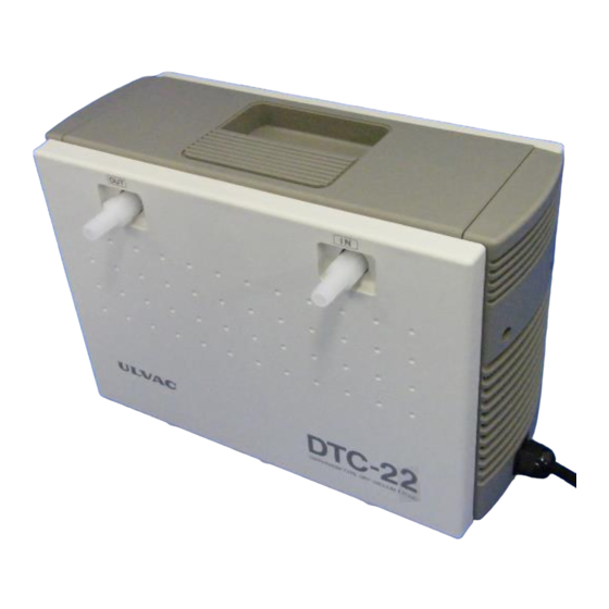
Diaphragm-type Dry Vacuum Pump
DTC-22A, DTC-22B, DTC-22C
Request to Users
Please read this manual thoroughly to ensure safe and
effective use of the equipment.
Keep this manual in a safe place.
Due to periodic improvements in performance, the
equipment described in this manual is subject to
changes in dimensions and specifications without prior
notice.
※ :It wishes attention because I will assume A,B,C
to be DTC-22 generically for the sign
that indicates the specification of the voltage.
ULVAC KIKO,Inc.
※
DTC-22
No.2001900-2-01-6
Advertisement
Table of Contents

Related Manuals for Ulvac DTC-22A


Summary of Contents for Ulvac DTC-22A
- Page 1 No.2001900-2-01-6 User’s Manual Diaphragm-type Dry Vacuum Pump DTC-22A, DTC-22B, DTC-22C ※ DTC-22 Request to Users Please read this manual thoroughly to ensure safe and effective use of the equipment. Keep this manual in a safe place. Due to periodic improvements in performance, the...
- Page 2 Declaration of Conformity Company:ULVAC KIKO,Inc. Address:291-7 Chausubaru Saito-city,Miyazaki (ZIP Cord:881-0037) Japan. This declaration is issued under the sole responsibility of the manufacturer. In accordance with the following Directive: 2006/42/EC Machinery Directive 2011/65/EU+(EU)2015/863 RoHS Directive declare under our sole responsibility that the product,...
- Page 3 Declaration of Conformity Company:ULVAC KIKO,Inc. Address:291-7 Chausubaru Saito-city,Miyazaki (ZIP Cord:881-0037) Japan. This declaration is issued under the sole responsibility of the manufacturer. In accordance with the following Directive: Supply of Machinery (Safety) Regulations 2008 (S.I. 2008 No. 1597, as amended by S.I. 2019 No. 696) The Restriction of the Use of Certain Hazardous Substances in Electrical and Electronic Equipment Regulations 2012 (S.I.
-
Page 4: Table Of Contents
Contents Pages with a shaded background are those which contain items related to safety. Before Using the Equipment ....................01 Checks When Opening Packaging ..................02 Using the Pump Safety ......................03 • Safety symbols ........................03 • Cautions for Safety in Use ....................04 1. - Page 5 Figures and Tables Fig.2.1 DTC-22(22A,22B、22C) Dimensions ..............2 Fig.3.1 Example of Piping Used When Evacuating a Vessel .......... 4 Table 1.1 Product Specifications ..................1 Table 6.1 Consumables List ....................6 Table 6.2 Locations for Maintenance and Inspection............7 Table 6.3 Troubleshooting List ..................13...
-
Page 6: Before Using The Equipment
Before Using the Equipment Thank you for purchasing this product. Your custom is very much appreciated. This pump is designed solely for vacuum discharge, and may malfunction or cause accidents if not handled appropriately. Read the manual thoroughly, and pay due attention to inspections, maintenance, and safety. -
Page 7: Checks When Opening Packaging
Checks When Opening Packaging Check the following after opening the packaging. (1) Is the product as you requested? (2) Are the accessories and necessary parts included? Standard accessories ・User’s manual -------------------- x 1 ・Inlet and outlet caps (fitted to inlet and outlet) -------------------- x 2 (3) Is the pump damaged in any way? (4) Are any external screws or inlet and outlet pipes loose? Are any components missing? -
Page 8: Using The Pump Safety
Using the Pump Safety To ensure that the pump is handled correctly, read this section thoroughly before use. This manual and the warning labels on the pump include safety icons as an aid to understanding safety requirements. These safety icons warn the operator and others of possible dangers and damage and should always be followed. - Page 9 • Cautions for Safety in Use Danger Applications This pump is not designed to be explosion-proof, and should therefore not be used to discharge explosive gases. In addition to discharge of gas via the outlet, gas may also leak from other parts of the pump, and it should therefore not be used with toxic gases.
- Page 10 (16) Please exchange the consumable parts to prevent the leakage from the pump every 5000 hours. ( The bearing is excluded.) (17) Please take shelter at once when the gas leaks by any chance due to the breakdown of the pump.
- Page 11 Warning Installation Do not use the pump in an explosive atmosphere. Such use may result in injury and fire. Ensure that there are no inflammable materials such as solvents in the vicinity when using the pump. Ensure that the motor is freely ventilated to prevent overheating which may result in fire or burns.
- Page 12 Warning Operation (12) This pump is not designed to be explosion-proof. When using the pump, ensure that there are no inflammable materials such as solvents, or explosive gases, in the vicinity. Use under such conditions may result in injury or fire. (13) Inserting fingers or objects into the motor inlet may result in electric shock, injury, or fire.
- Page 13 Caution Maintenance and Repair Dispose in accordance with legislation for disposal and cleaning of waste products, handle as industrial waste, and do not incinerate. Toxic fluorine gas is generated by incineration of fluorine-based plastics. (10) If the pump ceases operation, turn power OFF (set switch to O) immediately to prevent accidents, turn off the main disconnection device, and contact your dealer or the manufacturer for inspection and repair.
- Page 14 Note Installation Ingestion of liquids or compressed and gases into the pump will result in damage and prevent proper operation. Ingestion of rubbish and dust in the air entering the pump will interfere with its proper function. If the air is likely to contain rubbish or dust, a filter should be fitted to the inlet to protect the pump. Ducting should always be fitted to the pump outlet if toxic corrosive gases, or steam, enters the pump.
-
Page 15: Product Outline
(5) Ensure that the gas entering the pump does not contain rubbish, dust, or water (except steam). (6) Do not operate the pump for long periods at near-atmospheric pressure. 1.2 Specifications Table 1.1 Product Specifications Model DTC-22A DTC-22B DTC-22C 50Hz 20L/min Discharge rate 60Hz... -
Page 16: Thermal Protector
1.3 Thermal Protector 1) This pump is fitted with an automatic reset thermal protector for overload protection. This device shuts off the motor power supply circuit automatically to prevent burn-out if the motor temperature rises due to a pump fault which prevents rotation, or if load becomes excessive. 2) It is recommended that additional protective devices (eg. -
Page 17: Installation And Storage
3. Installation and Storage 3.1 Cautions for Installation and Storage Warning See Warning (1)(2)(3)(5)(6)(7)(8)(9)(10)(11), P06 Caution See Caution (1)(2)(3), P07 See Note (1), P08 Note (5)(6)(7)(8),P09 3.2 Environmental Conditions for Installation, Storage, and Operation The fine clearances used in this pump require that the following conditions be satisfied during storage, installation, and operation. -
Page 18: Cautions For Safety In Use
3.5 Piping 1) Install piping carefully to prevent leaks. 2) Piping connected to the inlet should be at least 5 mm inside diameter. 3) Ensure that piping connected to the outlet does not cause back pressure. Maximum back pressure is 0.03 MPa (gauge pressure). 4) In case of selecting the inlet pipe and exhaust pipe that are not from our products, please select the exhaust pipe that has same or larger inner diameter length with the inlet pipe. -
Page 19: Starting In Cold Weather
4.3 Starting in Cold weather (In door Use only) Cold weather will increase the viscosity of bearing grease and harden diaphragms, resulting in the pump being difficult to start. Follow the procedure below in such conditions. 1) Turn the switch ON/OFF 2~3 times with the inlet open to atmosphere until the pump starts. If the pump still does not start, raise the ambient temperature to beyond 0°C. -
Page 20: Maintenance, Inspection, And Repair
6. Maintenance, Inspection, and Repair 6.1. Cautions for Maintenance, Inspection, and Repair Danger See Danger (3), P04 See Warning (4) , P06 Warning (15)(16),P07 Caution See Caution (9)(10)(11), P08 Note See Note (12), P09 Maintenance and repair by the customer’s repair technician is limited to the following procedures. Do not undertake other repairs, or make modifications other than the standard options supplied by the manufacturer. -
Page 21: Content Of Contact To Our Service Section
<Replacement Guide> Replace or clean components if performance is reduced or the following symptoms become apparent. Table 6.2 Locations for Maintenance and Inspection Period of Method of Inspection item Replacement guidelines operation inspection Wear of PTFE components, Visual Diaphragms deformation, hardening, or cracking of inspection rubber components Inlet and outlet valves... -
Page 22: Replacing Diaphragms
1) Replacing Diaphragms (It is recommended that both diaphragms be replaced simultaneously.) Caution! Where gloves when attaching or removing the diaphragms. There is a danger of injuries. Use toolsNo.1,2,3,4,5,6、7 and8 listed above 1) -1. DTC-22 Truss head screw Hex socket head bolt Truss head (M4x10) (M6x25) - Page 23 (5) Withdraw the connecting tube from the valve retainer, and disassemble the left and right pump heads. See Photo 5. Bottom dead center Top dead center Diaphragm Spacer Connecting rod Photo 8 Photo 9 Photo 10 (6) When one diaphragm is pushed downwards (to bottom dead center), the other diaphragm rises (to top dead center).
- Page 24 (13) The pump head spacer is inserted between the pump head and the casing as shown in Photo 14. Note: Insert the pump head spacer in the same place as the place that has adhered. It puts it in the interior. Photo14 (14) The pump head is fixed with hex socket head bolts (M6X25).
-
Page 25: Replacing Inlet And Outlet Valves
2) Replacing Inlet and Outlet Valves (it is recommended that valves be replaced simultaneously with diaphragms) Use tools No.1, 2, 3, 4, 6, 7and 8. Cross recessed Pan Head Screw (M4x16) Valve retainer 2) -1. DTC-22 (1) Remove the front panel, top panel, and pump head cover. -
Page 26: Replacing O Rings
3) Replacing O Rings (it is recommended that O rings be replaced simultaneously with diaphragms) Use tools No.1, 2, 3, 4, 5, 6、7and 8. O ring (AS568-110) O ring O ring (S-24) (P-10A) Photo 20 Photo 21 Photo 22 (1) Remove the pump head from the casing, and remove the valve retainer. Use the procedure described in 2) Replacing Inlet and Outlet Valves, (1)~(2). -
Page 27: Troubleshooting List
6.6 Troubleshooting List Table 6.3 Troubleshooting List Problem Causes Solutions Reference (1) Not connected to power supply. (1) Connect power supply. (2) Switch is OFF. (2) Set switch to I. (3) Ensure that voltage variation is (3) Problem with power supply voltage. within +/-10%. -
Page 28: In Conclusion
7. In Conclusion Please contact the manufacturer’s sales division if you have any questions. Warranty (1) The warranty for this pump (this equipment) extends for a period of one year from the date of shipment. (2) Any malfunctions or defects which occur under normal usage conditions during the warranty period will be repaired free of charge. -
Page 29: Usage Status Check Sheet
Usage Status Check Sheet (for use in Instruction Manual) * For the purpose of safety control of repair personnel, fill in within the heavy line frame and attach the sheet to the item of which repair is requested. * In case this sheet were not attached or filled in, your request of repair and service may not be accepted. - Page 30 株式会社アルバック 規格品事業部 東日本営業部 〒253-8543 神奈川県茅ヶ崎市萩園2500 TEL:0467-89-2416 株式会社アルバック 規格品事業部 西日本営業部 〒532-0003 大阪府大阪市淀川区宮原3-3-31 上村ニッセイビル5F TEL:06-6397-2286 ULVAC KIKO,Inc. https://ulvac-kiko.com/en Please contact us for products, Service Base or other Inquiries from here. https://showcase.ulvac.co.jp/en/ ULVAC,Inc. Components Division 2500 Hagisono, Chigasaki, Kanagawa, 253-8543, Japan TEL:+81-467-89-2261...
Need help?
Do you have a question about the DTC-22A and is the answer not in the manual?
Questions and answers