Table of Contents
Advertisement
Quick Links
No.29700-2-03-8
Instruction Manual
High Vacuum Diaphragm Type
Dry Vacuum Pump
DTU-20x
(X: A=100V, B=115V, C=200V, D=220V, E=230V)
Request to Users
Please read this manual thoroughly to ensure safe and
effective use of the equipment.
Keep this manual in a safe place.
Due to periodic improvements in performance, the
equipment described in this manual is subject to
changes in dimensions and specifications without prior
notice.
ULVAC KIKO ,Inc.
Advertisement
Table of Contents

Related Manuals for Ulvac DTU-20 Series


Summary of Contents for Ulvac DTU-20 Series
- Page 1 Please read this manual thoroughly to ensure safe and effective use of the equipment. Keep this manual in a safe place. Due to periodic improvements in performance, the equipment described in this manual is subject to changes in dimensions and specifications without prior notice. ULVAC KIKO ,Inc.
- Page 2 Declaration of Conformity Company:ULVAC KIKO,Inc. Address:291-7 Chausubaru Saito-city,Miyazaki (ZIP Cord:881-0037) Japan. This declaration is issued under the sole responsibility of the manufacturer. In accordance with the following Directive: 2006/42/EC Machinery Directive 2011/65/EU+(EU)2015/863 RoHS Directive declare under our sole responsibility that the product,...
- Page 3 Declaration of Conformity Company:ULVAC KIKO,Inc. Address:291-7 Chausubaru Saito-city,Miyazaki (ZIP Cord:881-0037) Japan. This declaration is issued under the sole responsibility of the manufacturer. In accordance with the following Directive: Supply of Machinery (Safety) Regulations 2008 (S.I. 2008 No. 1597, as amended by S.I. 2019 No. 696) The Restriction of the Use of Certain Hazardous Substances in Electrical and Electronic Equipment Regulations 2012 (S.I.
-
Page 4: Table Of Contents
CONTENTS Before Using the Equipment ····················································································· 01 Checks When Opening Packaging ············································································· 02 Using the Pump Safely ···························································································· 03 ・Safety icons ···································································································· 03 ・Cautions for Safety in Use ················································································· 04 1. Outline of Equipment ···························································································· 1 1-1. Intended Use and Prohibitions of Equipment ························································· 1 1-2. - Page 5 7. In Conclusion ···································································································· 19 ・Warranty ········································································································· 19 Disposal Parts Material Table Exploded view ························································ 20.21 ・Usage Status Check Sheet (For Instruction Manual) (Please use when requesting overhaul) ・Product information, service bases, and contact information Drawing List Fig. 2 -1 DTU-20 Appearance ···················································································· 3 Fig.
-
Page 6: Before Using The Equipment
Before Using the Equipment Thank you for purchasing this product. Your custom is very much appreciated. This pump is designed solely for vacuum discharge, and may malfunction or cause accidents if not handled appropriately. Read the manual thoroughly, and pay due attention to inspections, maintenance, and safety. - Page 7 Checks When Opening Packaging Check the following after opening the packaging. (1) Is the product as you requested? (2) Are the accessories and necessary parts included? Standard accessories ・User’s manual -------------------- x 1 ・Inlet and outlet caps (fitted to inlet and outlet) -------------------- x 2 (3) Is the pump damaged in any way? (4) Are any external screws or inlet and outlet pipes loose? Are any components missing?
-
Page 8: Using The Pump Safely
Using the Pump Safely To ensure that the pump is handled correctly, read this section thoroughly before use. This manual and the warning labels on the pump include safety icons as an aid to understanding safety requirements. These safety icons warn the operator and others of possible dangers and damage and should always be followed. -
Page 9: Cautions For Safety In Use
・Cautions for Safety in Use Danger Applications This pump is not designed to be explosion-proof, and should therefore not be used to discharge explosive gases. In addition to discharge of gas via the outlet, gas may also leak from other parts of the pump, and it should therefore not be used with toxic gases. - Page 10 Danger (17) Please take shelter at once when the gas leaks by any chance due to the breakdown of the pump. And, please ventilate the air in the room enough. Moreover, please enter the room of the device after wearing the hazard mask when you confirm the device. Do not detach the hazard mask until safety is confirmed.
- Page 11 Warning Installation Do not use the pump in an explosive atmosphere. Such use may result in injury and fire. Ensure that there are no inflammable materials such as solvents in the vicinity when using the pump. Ensure that the motor is freely ventilated to prevent overheating which may result in fire or burns.
- Page 12 Caution Installation The fine clearances used in this pump require that the following conditions be satisfied during storage, installation, and operation. Ambient temperature of 5℃ to 40°C in temperature, Lower than 85% (relative humidity) in humidity . Other conditions for storage and operation. a) Level floor of sufficient strength.
- Page 13 Note Installation The pump may malfunction if it is subjected to shocks or tipped over on its side. Do not hold or push the tube at the top of the pump (see below). Damage to the tube may affect performance of he pump. Applications This pump is not designed to be corrosion-proof.
-
Page 14: Outline Of Equipment
1. Outline of Equipment 1-1. Intended Use and Prohibitions of Equipment This diaphragm type dry vacuum pump performs evacuation by reciprocating motion of rubber membrane (diaphragm). PTFE (corrosion resistance resin) used for parts exposing to gas obtained superior corrosion resistance. Please take note of the following prohibitions to use Equipment correctly. -
Page 15: Checks When Opening Packaging
1-3. Protector (thermal protector) This pump is fitted with an automatic reset thermal protection relay for overload protection. This device shuts off the motor power supply circuit automatically to prevent burn-out if the motor temperature rises due to a pump fault which prevents rotation, or if load becomes excessive. See "Warning"... -
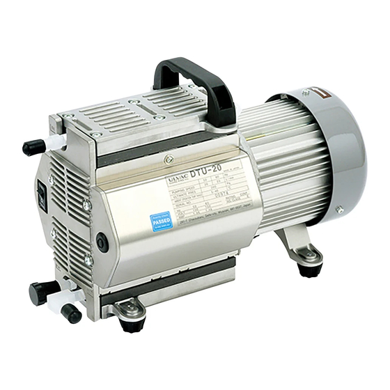
Page 16: Appearance
2. Appearance Fig2-1 DTU-20 Appearance 3... -
Page 17: Installation / Storage
3. Installation / Storage 3-1. Precautions in Installation / Storage See "Danger" (4) (5) (6) (24) (25) (26) (27) (28) on P. 04. DANGER See "Warning" (1) (2) (3) (5) (6) (7) (8) (9) (10) (11) (12) (13) (14) on P. 06. WARNING See "Caution"(1) (2) (3) (4) on P. -
Page 18: Electric Wiring
3-4 Electric wiring 1) Detach rubber screen that attached to the inlet / exhaust pipe. 2) Confirm that the pump switch is set to OFF (pushed to ○ side) and connect it to power source. Connect the ground lead without exception at this time. CAUTION 3) Turn the switch ON (push to -... -
Page 19: Piping
3-6 Piping 1) Connect piping tightly so that no leak is found. 2) Use the pipe larger than 6 mm internal diameter (close to AWG 3) for inlet / exhaust port piping. 3) In case the back pressure is inevitable, make it less than 0.03MPa. 4) Piping for evacuation of the container shall have a blocking valve as shown on Fig. -
Page 20: Caution In Operation
4-2 When Thermal Protector Operated 1) When a thermal protector operated, at first turn off the pump power supply (push to ○ side) and disconnect power cable. Contact Ulvac or local agent. Temperature of the pump is very high at this time. -
Page 21: Starting In Cold Ambient
4-3 Starting in Cold Ambient In the cold ambient, there is a case to confront with difficulty in start because of hardened grease and diaphragm of the bearing. When it is difficult to start, follow the procedure described below. 1) Open the inlet port to atmosphere and repeat switch ON, OFF two or three times until the pump starts. -
Page 22: Pump Performance
"Ultimate Pressure" mentioned in Catalog and this Instruction Manual means "the lowest pressure obtained by a pump in the status that no gas is filled from the pump inlet port (idling operation status)”. Ulvac is measuring the pressure by connecting a film-type (diaphragm type) vacuum gauge to inlet port of the pump. -
Page 23: Maintenance Inspection Repair
NOTE Maintenance / repair range that allowed to perform by repair engineers in the Customers are the following 2 items. Do not conduct the other repair and remodeling other than Ulvac standard option. 1) Replacement of diaphragms 2) Replacement of valves 6-2 Maintenance During an operation of the vacuum pump, check the following items at least once in 3 days. -
Page 24: Periodic Inspection
Conduct periodic inspections of consumable parts in every 3,000 hours after started using and replace parts according to "Guideline of Parts Replacement". Replacement method [6-4. refer to replacement] of consumable part. In case there is no repair engineer, Ulvac Service Section shall be happy to replace the parts. -
Page 25: Replacement Of Consumable Parts
Prepare the following tools and refer to drawing when working replacement. When having difficulty in preparing the tools, ask Ulvac Service Section. Phillips screwdriver: No. 2 Torque driver (plus) set tightening torque to 4N∙m Spanner: Opposite sides 13 mm (0.5") (thickness lower than 5.5 mm (0.2")),... -
Page 26: At The Same Time
1) Replacement of diaphragm valves. It is recommended to replace all sheets at the same time. When working on replacement, wear gloves always. There is risk of injury. CAUTION (2) Valve retainer cover (Upper and lower) (5) Handle (3) Valve retainer (Upper and lower) (4) Connecting pipe (Upper and lower) - Page 27 Mount upper level valve in orientation as shown in right drawing. Upper level pump head mounting direction (Notch direction) Mount the lower level valve in orientation as shown in left drawing Lower level pump head mounting direction (Notch direction) Open hole valve 14...
- Page 28 Tools to use No. 1, 2, 3, 4, 5 Replacement work procedure (Replacement procedure from the upper level) Detach handle ⑤ at first. Detach panel ① of pump left and right. Detach switch plug terminal and ground lead of the side that power cord is connected. Loosen 6 pan head small screws and detach Casing Cover ⑦.
-
Page 29: Replacement Of Bearing
Check the procedure from the item Before turning the switch ON, check the work, particularly the area related to the power supply, again and start the pump operation. 2) Replacement of bearing Request Ulvac Service Section. 16... -
Page 30: Trouble Check List
6-5 Trouble Check List Table 6 -3 Trouble Check List Trouble Refer Cause How to resolve problem contents ence (1) Not connected to power supply (1) Connected to power supply (2) Switch is not turned ON (2) Push switch to | side (3) Adjust voltage fluctuation to lower than (3) Abnormal voltage of power source input ±10%... - Page 31 Trouble Refer Cause How to resolve problem contents ence (1) Performing continuous operation in the (1) Do not conduct continuous operation in Temperature of status that absorption gas pressure is high vicinity of atmospheric pressure pump surface is abnormally high (2) Mount refrigerating machine such as gas (higher than room (2) Absorption gas is high temperature...
- Page 32 7. In Conclusion Please contact the manufacturer’s sales division if you have any questions. Warranty (1) The warranty for this pump (this equipment) extends for a period of one year from the date of shipment. (2) Any malfunctions or defects which occur under normal usage conditions during the warranty period will be repaired free of charge.
- Page 33 Disposal When disposing of a scrapping pump, please handle according to the laws legislated by country and the ordinance issued by local government. When disposing of poisonous gas that endangers the human body, consign scrapping processing with a specialized disposing vendor.
- Page 34 Exploded view 21...
- Page 35 Usage Status Check Sheet (for use in Instruction Manual) * For the purpose of safety control of repair personnel, fill in within the heavy line frame and attach the sheet to the item of which repair is requested. * In case this sheet were not attached or filled in, your request of repair and service may not be accepted.
- Page 36 No.62400-2-02-10 アルバック機工株式会社 https://ulvac-kiko.com 製品情報・サービス拠点・お問い合わせはこちらから https://showcase.ulvac.co.jp/ja/ 株式会社アルバック コンポーネント事業本部 営業部 〒253-8543 神奈川県茅ヶ崎市萩園2500 TEL:0467-89-2416 ULVAC KIKO,Inc. https://ulvac-kiko.com/en Please contact us for products, Service Base or other Inquiries from here. https://showcase.ulvac.co.jp/en/ ULVAC,Inc. Components Business HQ 2500 Hagisono, Chigasaki, Kanagawa, 253-8543, Japan TEL:+81-467-89-2261...
Need help?
Do you have a question about the DTU-20 Series and is the answer not in the manual?
Questions and answers